semi合集-English.pdf - 第5842页
SEMI P32-1104 © SEMI 1998, 2004 2 6 Apparatus 6.1 Measurement Equipment 6.1.1 Flam e Atomic Absorption Spectrom eter (F-AAS) and ICP-MS c an be applied to t he dry as hing me thod. 6.1.2 Graphite Furn ace Atomic Absorpti…

SEMI P32-1104 © SEMI 1998, 2004 1
SEMI P32-1104
TEST METHOD FOR DETERMINATION OF TRACE METALS IN
PHOTORESIST
This test method was technically approved by the Global Micropatterning Committee and is the direct
responsibility of the Japanese Micropatterning Committee. Current edition approved by the Japanese
Regional Standards Committee on July 23, 2004. Initially available at www.semi.org August 2004; to be
published November 2004. Originally published September 1998.
1 Purpose
1.1 This document describes an outline of a
quantitative analysis method on trace metal
concentration. This standard is intended to promote
communication between users and suppliers.
2 Scope
2.1 This document applies to a measurement of trace
metal concentration in ppb level in photoresist by
instrumental techniques, such as Atomic Absorption
Spectrometry, Plasma Ion Source Mass Spectrometry,
and Inductively Coupled Plasma Atomic Emission
Spectrometry.
2.2 Object metals in this measurement are Al, Ca, Cr,
Cu, Fe, Mg, Mn, Ni, K, and Na.
2.3 Either additional metals or fewer can be agreed
upon between users and suppliers and are added to the
measurement list.
2.4 The following method has given satisfactory results
in determining trace metal impurities at the specified
value for each of the target trace metals. Alternative
methods or conditions may be used as long as
appropriate studies demonstrate recovery between
75%–125% of a known sample spike for half the
specification value. The results should be reported as
within specification (below a certain value) or not in
specification only (SEMI C1).
NOTICE: This standard does not purport to address
safety issues, if any, associated with its use. It is the
responsibility of the users of this standard to establish
appropriate safety and health practices and determine
the applicability of regulatory or other limitations prior
to use.
3 Referenced Standards
3.1 SEMI Standard
SEMI C1 — Guide for the Analysis of Liquid
Chemicals
3.2 ASTM Standard
ASTM D1193 — Standard Specification for Reagent
Water
4 Summary of Method
4.1 Photoresist test solution is prepared by dry ashing
method or direct method. Then trace metals in the test
solution are measured by Atomic Absorption
Spectrometry, Plasma Ion Source Mass Spectrometry,
or Inductively Coupled Plasma Atomic Emission
Spectrometry. The trace metal concentration is
determined using a working curve, which is obtained by
measuring a standard solution.
5 Terminology
5.1 Definitions
5.1.1 blank test — a measurement without the object
photoresist, which is performed under the standard
procedures.
5.1.2 dilution factor — numerical number that
indicates final amount of solution divided by the initial
amount of solution in the preparation of the photoresist
process.
5.1.3 direct method — a sample preparation method
for preparing samples for direct trace metal in
photoresist. The materials are diluted with a solvent and
then analyzed by the appropriate analytical instrument.
5.1.4 dry ashing method — a sample preparation
method for preparing samples used in measuring trace
metals in the photoresist. The photoresist is evaporated
and decomposed to ash by heating. The ash is dissolved
in a volumetric flask with acid and aqueous reagent,
and then analyzed by the appropriate analytical
instrument.
5.1.5 plasma ion source mass spectrometry — a
method that isolates and measures quantitative metal
element by mass spectrometer using plasma as
excitation source. Inductively Coupled Plasma Mass
Spectrometry (ICP-MS) and Microwave Induced
Plasma Mass Spectrometry (MIP-MS) belong to this
category.
5.1.6 working curve — the relationship between known
metal concentrations prepared by standard solutions and
the observed values of instrumental analysis.
SEMI P32-1104 © SEMI 1998, 2004 2
6 Apparatus
6.1 Measurement Equipment
6.1.1 Flame Atomic Absorption Spectrometer (F-AAS)
and ICP-MS can be applied to the dry ashing method.
6.1.2 Graphite Furnace Atomic Absorption
Spectrometer (GF-AAS), Electrothermal Atomization
Atomic Absorption Spectrometer (ETA-AAS), ICP-
MS, MIP-MS, and Inductively Coupled Plasma Atomic
Emission Spectrometer (ICP-AES) can be applied to
the direct method.
6.1.3 Instrument Condition — Recommended
instrumental conditions are summarized in Table 1 for
each target metal.
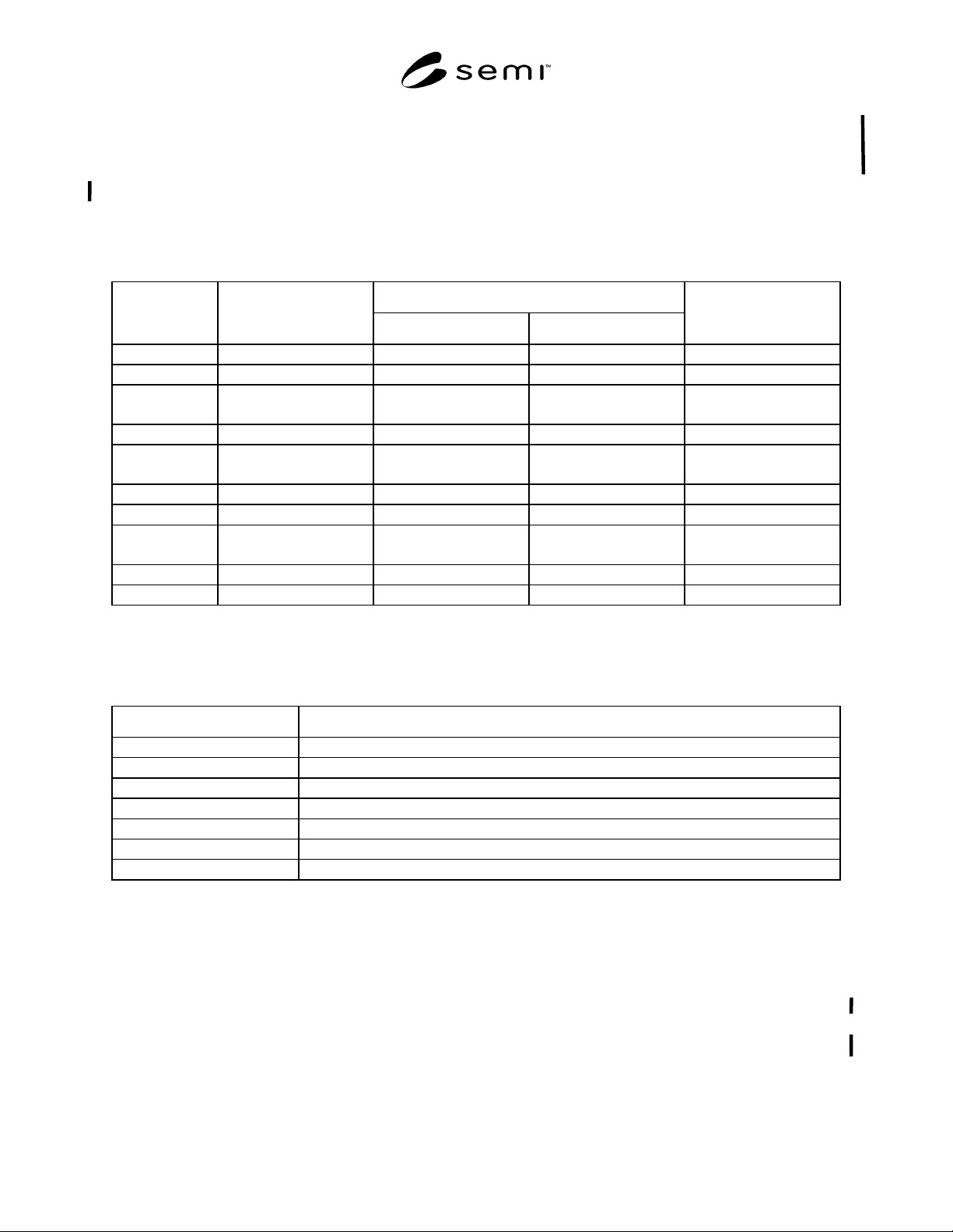
Table 1 Measurement Equipment and Metal Elements
Plasma Ion Source Mass Spectrometry
Element
Atomic Absorption
Spectroscopy
ICP-MS (Note 1) MIP-MS (Note 2)
ICP-Atomic Emission
Spectrometer
Al 309.2 nm
27
Al
27
Al 396.2 nm
Ca 422.7 nm
40
Ca,
44
Ca (Note 3)
40
Ca 393.4 nm
Cr 357.9 nm
359.4 nm
52
Cr,
53
Cr
(Note 3)
52
Cr 267.7 nm
283.6 nm
Cu 324.7 nm
63
Cu,
65
Cu
63
Cu,
65
Cu 324.8 nm
Fe 248.3 nm
56
Fe,
54
Fe
(Note 3)
56
Fe,
54
Fe 259.9 nm
Mg 285.2 nm
24
Mg,
25
Mg,
26
Mg
24
Mg,
25
Mg,
26
Mg 279.6 nm
Mn 279.5 nm
55
Mn (Note 3)
55
Mn 257.6 nm
Ni 232.0 nm
341.4 nm
58
Ni,
60
Ni
(Note 3)
58
Ni,
60
Ni 221.6 nm
231.6 nm
K 766.5 nm
39
K,
41
K (Note 3)
39
K,
41
K 766.5 nm
Na 589.0 nm
23
Na
23
Na 589.0 nm
NOTE 1: ICP-MS — Ar is used as the plasma generation gas.
NOTE 2: MIP-MS — N
2
is used as the plasma generation gas.
NOTE 3: Beware of interfering ion (see Table 2).
Table 2 Interfering Ions
Object Metal Interfering Ion
39
K
38
Ar
1
H
41
K
40
Ar
1
H
40
Ca
40
Ar
52
Cr
40
Ar
12
C,
36
Ar
16
O,
38
Ar
14
N
55
Mn
40
Ar
14
C
1
H,
40
Ar
15
N,
38
Ar
16
O
1
H
56
Fe
40
Ar
16
O,
38
Ar
18
O
58
Ni
40
Ar
18
O
7 Vessels, Reagents, and Environment
7.1 Vessel
7.1.1 Quartz glass volumetric flask
7.1.2 Quartz glass measuring pipette
7.1.3 Quartz glass beaker
7.1.4 PTFE vessel
7.1.5 Platinum crucible
7.2 Reagents
7.2.1 DI Water — Resistivity ≥ 18.0 MΩ cm at 25°C
per ASTM D 1193.
7.2.2 Organic Reagent — Use commercially
guaranteed reagent for trace metal analysis.
7.2.3 Inorganic Reagent — Use commercially
guaranteed reagent for trace metal analysis.
7.2.4 Standard Reagent — Use the commercially
guaranteed reagents which have certified trace metals
concentration.
SEMI P32-1104 © SEMI 1998, 2004 3
7.3 Environment
7.3.1 The measurement is recommended to be
performed in a clean room or clean zone at constant
temperature. The stability of temperature should be
better than ± 2°C. Dry ashing method should be
performed in a draft chamber with HEPA filter, if
possible.
7.3.2 In the case of volumetric analysis, the
measurement environment is set to the standard
temperature of measuring tools such as volumetric flask
and measuring pipette.
8 Procedures
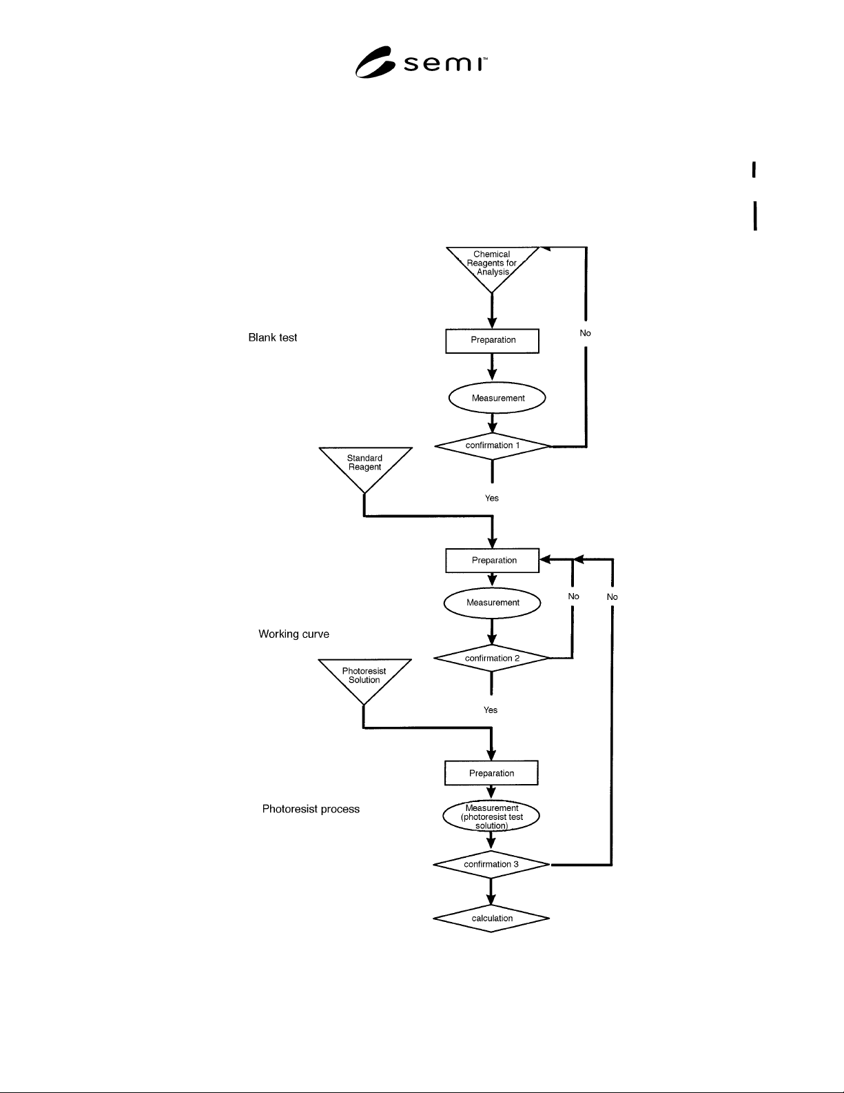
8.1 Flow Chart of Measurement — Refer to Figure 1
as suggested analysis process.
Figure 1
Flow Chart of Trace Metal Measurement