semi合集-English.pdf - 第6418页
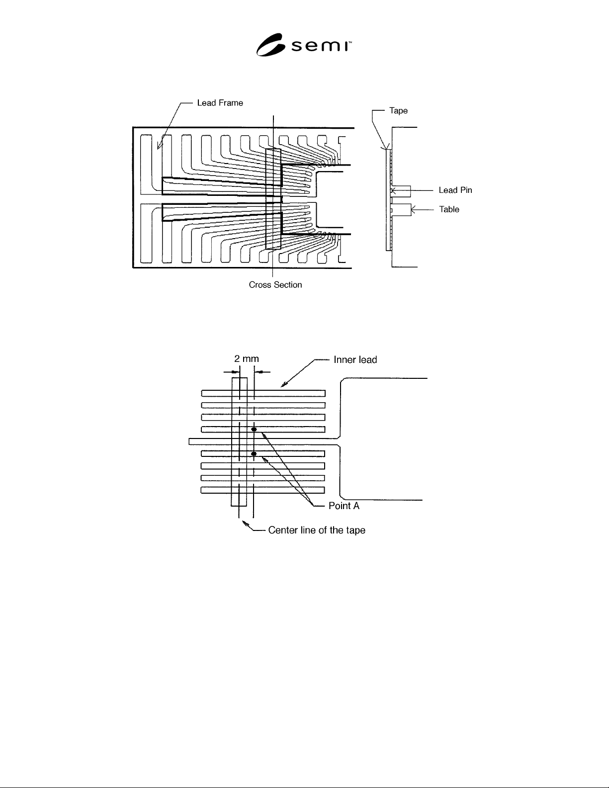
SEMI G75.2-069 8 © SEMI 1998 5 Figure 8 Relation of L eadframe and T able in Push-Down Method Figure 9 Probe Position over the Selected Inner Lead in Push-Down Method 6.2.4 Adjust the probe po sition until i t j ust touc…
SEMI G75.2-0698 © SEMI 1998 4
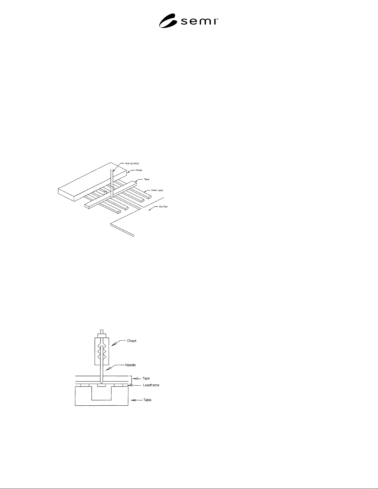
6.1.3 Position the hook under the tape between the tie
bar and its neighboring inner lead as shown in Figure 6.
Similar leads and hook position shall be selected for
other types of leadframes.
6.1.4 Adjust the hook position until it just touches the
tape and initiate the tensile tester in the up-mode.
Record the strength to break the adhesion between the
lead and the tape.
6.1.5 Repeat the test for each leadframe in the
samples.
6.1.6 Calculation
6.1.6.1 Discard the maximum and minimum values
recorded, and average the remainder.
Figure 6
Measurement of Pull-Up Strength
6.2 Push-Down Procedure
6.2.1 Set the tensile tester in the down-mode, and
adjust the rate to 100 mm/minute.
6.2.2 Place the leadframe on the table as shown in
Figures 7 and 8.
6.2.3 Position the probe at Point A over the selected
inner lead as shown in Figure 9.
Figure 7
Measurement of Push-Down Strength
(Cross-Section)
SEMI G75.2-0698 © SEMI 19985
Figure 8
Relation of Leadframe and Table in Push-Down Method
Figure 9
Probe Position over the Selected Inner Lead in Push-Down Method
6.2.4 Adjust the probe position until it just touches the inner lead and initiate the tensile tester in the down-mode.
Record the strength to break the adhesion between the inner lead and the tape.
6.2.5 Repeat the test for each of the test positions noted in Section 6.2.4.
6.2.6 Repeat the tests for each leadframe in the sample.
6.3 Calculation
6.3.1 Discard the maximum and minimum values recorded and average the remainder.

SEMI G75.2-0698 © SEMI 1998 6
7 Related Documents
7.1 JIS Specification
1
JIS K 6854 — Testing Methods for Peel Strength of
Adhesives
NOTICE: These standards do not purport to address
safety issues, if any, associated with their use. It is the
responsibility of the user of these standards to establish
appropriate safety and health practices and determine
the applicability of regulatory limitations prior to use.
SEMI makes no warranties or representations as to the
suitability of the standards set forth herein for any
particular application. The determination of the
suitability of the standard is solely the responsibility of
the user. Users are cautioned to refer to manufacturer’s
instructions, product labels, product data sheets, and
other relevant literature respecting any materials
mentioned herein. These standards are subject to
change without notice.
The user’s attention is called to the possibility that
compliance with this standard may require use of
copyrighted material or of an invention covered by
patent rights. By publication of this standard, SEMI
takes no position respecting the validity of any patent
rights or copyrights asserted in connection with any
item mentioned in this standard. Users of this standard
are expressly advised that determination of any such
patent rights or copyrights, and the risk of infringement
of such rights, are entirely their own responsibility.
1 Japanese Standards Association, 1-24, Akasaka 4 Chome, Minato-ku, Tokyo, Japan
Copyright by SEMI® (Semiconductor Equipment and Materials
International), 3081 Zanker Road, San Jose, CA 95134. Reproduction o
f
the contents in whole or in part is forbidden without express written
consent of SEMI.