semi合集-English.pdf - 第6459页
SEMI G76-0299 © SEMI 1999 15 Figure 9 Wakame Figure 10 Camber NOTICE: These standards do not purport to address sa fety issues, if any, associated w ith their use. It is the responsibility of the user of these standards …
SEMI G76-0299 © SEMI 1999 14
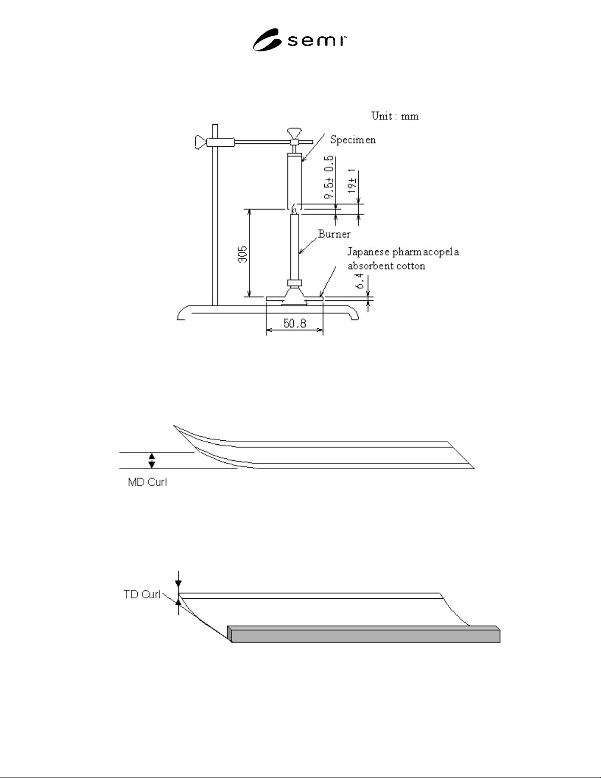
Figure 6
Measurement of Flammability
Figure 7
MD Curl
Figure 8
TD Curl
SEMI G76-0299 © SEMI 1999 15
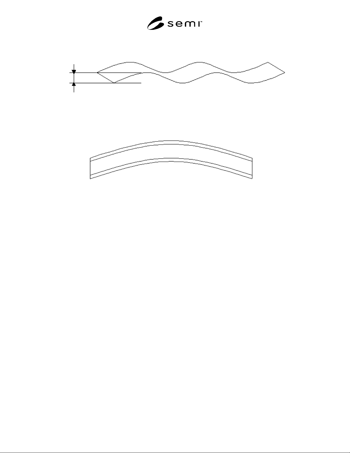
Figure 9
Wakame
Figure 10
Camber
NOTICE: These standards do not purport to address safety issues, if any, associated with their use. It is the
responsibility of the user of these standards to establish appropriate safety and health practices and determine the
applicability of regulatory limitations prior to use. SEMI makes no warranties or representations as to the suitability
of the standards set forth herein for any particular application. The determination of the suitability of the standard is
solely the responsibility of the user. Users are cautioned to refer to manufacturer' s instructions, product labels,
product data sheets, and other relevant literature respecting any materials mentioned herein. These standards are
subject to change without notice.
The user' s attention is called to the possibility that compliance with this standard may require use of copyrighted
material or of an invention covered by patent rights. By publication of this standard, SEMI takes no position
respecting the validity of any patent rights or copyrights asserted in connection with any item mentioned in this
standard. Users of this standard are expressly advised that determination of any such patent rights or copyrights, and
the risk of infringement of such rights, are entirely their own responsibility.
Copyright by SEMI® (Semiconductor Equipment and Materials
International), 3081 Zanker Road, San Jose, CA 95134. Reproduction o
f
the contents in whole or in part is forbidden without express written
consent of SEMI.

SEMI G77-0699 © SEMI 19991
SEMI G77-0699
SPECIFICATION FOR FRAME CASSETTE FOR 300 MM WAFERS
This test method was technically approved by the Global Assembly & Packaging Committee and is the direct
responsibility of the Japanese Packaging Committee. Current edition approved by the Japanese Regional
Standards Committee on March 17, 1999. Initially available at www.semi.org May 1999; to be published
June 1999.
1 Purpose
1.1 The purpose of this document is to specify the
mechanical features for a 300 mm wafer frame cassette
used between the wafer mounting process and the die-
bonding process.
2 Scope
2.1 This standard is intended to set an appropriate
level of specification that places minimal limits on
innovation while ensuring modularity and
interchangeability at all mechanical interfaces.
2.2 Only the physical interfaces for the frame cassette
are specified; no materials requirements or micro-
contamination limits are given. However, this
specification was written to allow for both metal and
plastic frame cassette designs.
2.3 This specification defines a 30 0 mm wafer frame
cassette that is intended for both manual and automated
transport. The frame cassette has the following
components and sub-components (“ ” indicates an
optional component):
2.3.1 Top
robotic handling flange (optional)
- top cover
2.3.2 Interior
- frame supports for 13 or 25 tape frames
- frame restraint
2.3.3 Sides
human handles (optional)
2.3.4 Rear
- rear cover
2.3.5 Bottom
- 2 bottom conveyor rails running along the
sides of the frame cassette
3 features that mate with kinematic coupling
pins and provide a 10 mm lead-in (optional)
4 frame cassette sending pads (optional)
3 Referenced Documents
3.1 SEMI Standards
SEMI E1.9 Provisional Mechanical Specification for
Cassettes Used to Transport and Store 300 mm Wafers
SEMI E15 Specification for Tool Load Port
SEMI E47.1 Provisional Mechanical Specification
for Boxes and Pods Used to Transport and Store 300
mm Wafers
SEMI E57 Provisional Mechanical Specification for
Kinematic Couplings Used to Align and Support 300
mm Wafer Carriers
SEMI G74 Specification for Tape Frame for 300
mm Wafers
SEMI S8 Safety Guidelines for Ergonomics/Human
Factors Engineering of Semiconductor Manufacturing
Equipment
4 Terminology
4.1 bilaterial datum plane
a vertical plane that
bisects the tape frames and that is perpendicular to both
the horizontal and facial datum planes (as defined in
SEMI E57).
4.2 conveyor rails
parallel surfaces on the bottom
of the cassette for supporting the cassette on roller
conveyors.
4.3 facial datum plane a vertical plane that bisects
the tape frames and that is parallel to the front side of
the frame cassette (where tape frames are removed or
inserted). On tool load ports, it is also parallel to the
load face plane specified in SEMI E15 on the side of
the tool where the frame cassette is loaded and
unloaded (as defined in SEMI E57).
4.4 frame cassette an open structure that holds one
or more tape frames.
4.5 horizontal datum plane a horizontal plane from
which projects the kinematic coupling pins on which
the frame cassette sits. On tool load ports, it is at the
load height specified in SEMI E15 and might not be
physically realized as a surface (as defined in SEMI
E57).