semi合集-English.pdf - 第428页
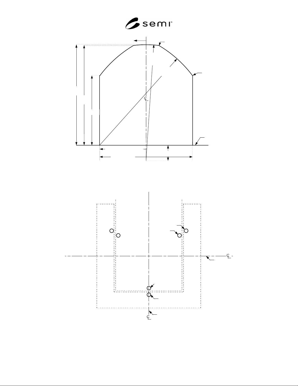
SEMI E57-0305 © SEMI 1996, 2005 4 horizontal dat um pl ane r 94 = 2 ± 0.1 (blend) fin al ro ughness height of over-all surface finish r 9 7 0.30 m (R a ) ( z 93 12.910) ( z 94 13) ( z 92 9) d 91 = 12 ± 0.05 …

SEMI E57-0305 © SEMI 1996, 2005 3
SEMI M31 — Provisional Mechanical Specification for Front-Opening Shipping Box Used to Transport and Ship
300 mm Wafers
6.2 Other Documents
Alexander H. Slocum, Precision Machine Design, Society of Manufacturing Engineers, Item Code 2597, 1992
(originally published by Prentice-Hall, 1992)
Table 1 Kinematic Coupling Pin Dimensions
Symbol Used Value Specified Dimension Description
d91 12 ± 0.05 mm
(0.4724 ± 0.002 in.)
Diameter of pin centered on the center axis line.
r92 6 mm (0.2362 in.) Radial distance from the center axis line to the origin of the shoulder radius r95.
r93 15 ± 0.05 mm
(0.5906 ± 0.002 in.)
Radial distance from the intersection of the center axis line and z91 to the top of the
pin.
r94 2 ± 0.1 mm
(0.0787 ± 0.004 in.)
Blend radius for the intersection of r93 and r95.
r95 15 ± 0.05 mm
(0.5906 ± 0.002 in.)
Radial distance from the intersection of the horizontal datum plane and r92 to the far
shoulder of the pin.
r96 2 ± 0.1 mm
(0.0787 ± 0.004 in.)
Blend radius for the intersection of r95 and d91.
r97
0.30 m (12 in.)
maximum
Roughness (R
a
) as defined in ISO 4287.
z91 2 mm (0.08 in.) Vertical distance from the horizontal datum plane to the origin of top radius r93.
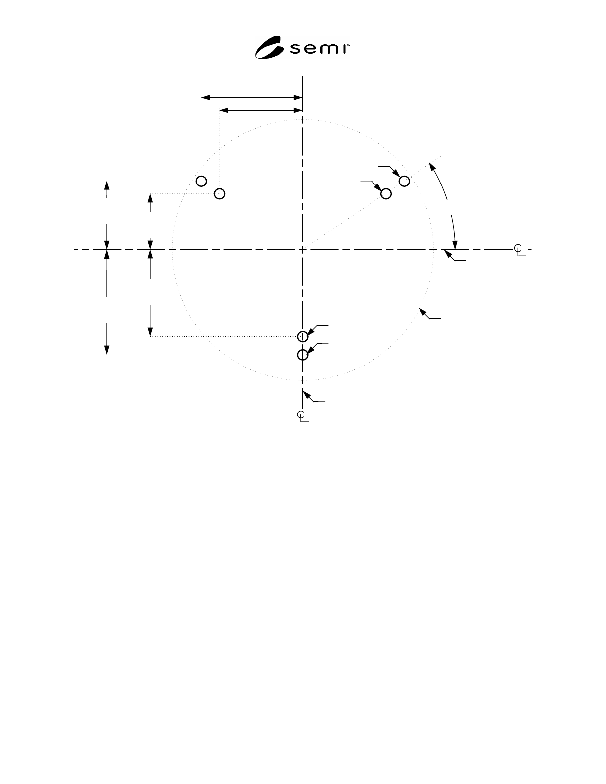
Table 2 Distances to the Center Axis Lines of the Coupling Pins
Symbol Used Value Specified Datum Plane
Measured from
Pin Center Axis Line(s)
Measured to
r97
0.30 m (12 in.)
maximum
Roughness (R
a
) as defined in ISO 4287 r97
x91 115 ± 0.05 mm
(4.5276 ± 0.002 in.)
bilateral front right and left
primary
x92 92 ± 0.05 mm
(3.6220 ± 0.002 in.)
bilateral front right and left
secondary
y91 80 ± 0.05 mm
(3.1496 ± 0.002 in.)
facial front right and left
primary
y92 120 ± 0.05 mm
(4.7244 ± 0.002 in.)
facial rear
primary
y93 64 ± 0.05 mm
(2.5197 ± 0.002 in.)
facial front right and left
secondary
y94 96 ± 0.05 mm
(3.7795 ± 0.002 in.)
facial rear
secondary
SEMI E57-0305 © SEMI 1996, 2005 4
horizontal
datum plane
r94 = 2 ± 0.1
(blend)
final roughness
height of over-all
surface finish
r9
7
0.30
m (R
a
)
(
z
93
12.910)
(
z
94
13)
(
z
92
9)
d
91 = 12 ± 0.05
r92 = 6 ± 0 (origin of r95)
(
r
91
1.637)
r96 = 2 ± 0.1
(blend)
r95
= 15 ± 0.05
r93
= 15
± 0.05
z91= 2 ± 0
Figure 1
Kinematic Coupling Pin Shape
tool
load-port
robotic
arm
primary pin
facial
datum
plane
bilateral datum plane
secondary pin
primary pin
secondary
pin
Figure 2
Primary and Secondary Kinematic Coupling Pins
SEMI E57-0305 © SEMI 1996, 2005 5
Figure 3
Kinematic Coupling Pin Locations
y 92
= 120 ± 0.05
y
93
= 64 ± 0.05
y 94
= 96 ± 0.05
y 91
= 80 ± 0.05
primary pin
facial
datum
plane
x
91 = 115 ± 0.05
x92
=92 ± 0.05
300-mm
wafer
bilateral datum plane
34.8°)
secondary pin
primary pin
secondary
pin