semi合集-English.pdf - 第136页
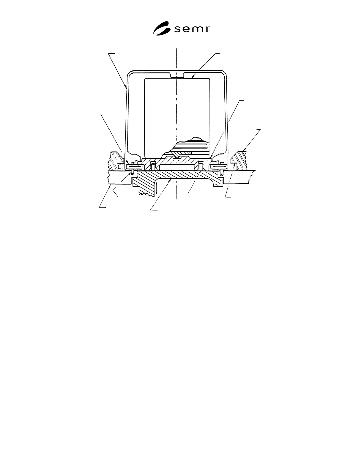
SEMI E19-0697 © SEMI 1991, 2002 4 Box C asse tt e Bo x Guide Rail Latch Cavity Registration Pin Port Door Port Plate Latch Pin Box Latch Figure 1 Port Terminology

SEMI E19-0697 © SEMI 1991, 2002 3
between registration pins and holes is considered. This
is to ensure interference free passage of the box door
through the port opening.
7.2.5.2 The base of the box body shall fit freely but
with close tolerance between the guide rails (B1, B2,
and B9), which not only hold the box in place while the
port is open, but also provide proper alignment for the
closure of the box at the end of the open/shut cycle.
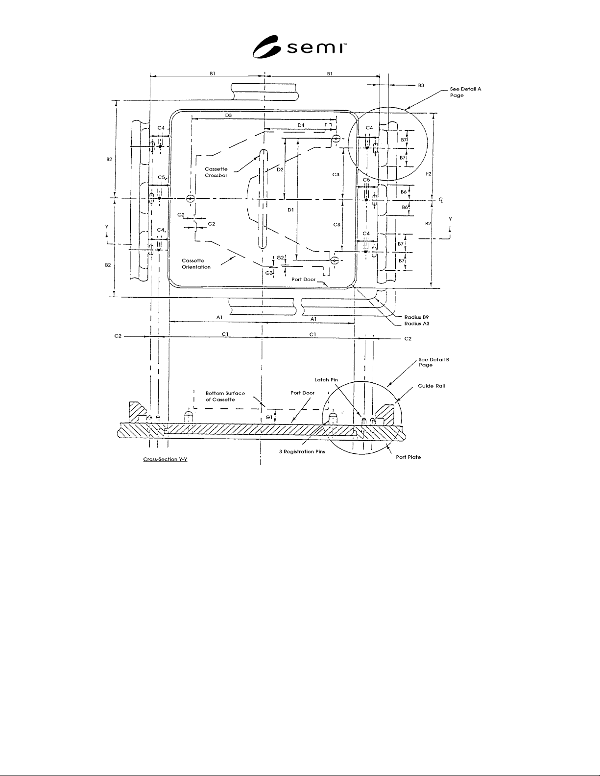
7.2.5.3 The bottom surface of the box requires three
registration holes to engage with the registration pins on
the port. The registration pins shall be positioned in the
door bottom so that the registration pins prevent seating
of the box with the port in the event that the box is
improperly rotated by 180 degrees from the correct
orientation. The correct orientation is illustrated in
Figure 2.
7.2.5.4 The perimeter of the bottom surface of the box
body shall be continuous (except possibly at the latch
locations) and shall be positioned against the port
surface. This positioning assures the activation of an
optional limit switch placed in an unspecified location
along the port perimeter for the sensing of proper box
placement.
7.2.5.5 Each box door latch requires a hole to engage
its corresponding port latch pin. The hole shall be
elongated to provide a target area for the activated pin
(box door open) as shown by dimension C8. A
protrusion from each latch shall engage with its
corresponding cavity in the guide rail to prevent the
removal of the box while the port is open.
7.2.5.6 The center of the cassette crossbar shall
coincide with the center of the box door, with the
cassette orientated as shown in Figure 2. The top
surface of the box door requires registration bars that
hold the cassette in place. The horizontal cassette
movement is limited by the tolerances G2. The vertical
position of the cassette while located on the box door is
specified by the distance G1 between the top of the port
surface and the bottom surface of the cassette.
7.2.5.7 The external top of the box shall not exceed
the top of the cassette by more than two inches. This is
to prevent possible interference between the box and
the equipment.
8 References
The following articles describe the standard mechanical
interface concept:
8.1 “The Challenge to Control Contamination: A
Novel Technique for the IC Process,” The Journal of
Environmental Sciences (May/June 1984) , page 23.
8.2 “SMIF, A Technology for Wafer Cassette Transfer
in VLSI Manufacturing,” Solid State Technology (July
1984), page 111.
SEMI E19-0697 © SEMI 1991, 2002 4
Box
C
asse
tt
e
Bo
x
Guide
Rail
Latch
Cavity
Registration
Pin
Port
Door
Port
Plate
Latch
Pin
Box
Latch
Figure 1
Port Terminology
SEMI E19-0697 © SEMI 1991, 2002 5
Figure 2