semi合集-English.pdf - 第202页
SEMI E26-92 © SEMI 1992, 2004 1 SEMI E26-92 (Withdrawn 1104) RADIAL CLUSTER TOOL FOOTPRINT STANDARD This standard was technically appr oved by the Global Physical Interfaces & Carriers Com mittee and is the direct re…

SEMI E25-92 © SEMI 1992, 2004 4
SEMI E26 — Radial Cluster Tool: Module Footprint
Standard.
NOTICE: SEMI makes no warranties or
representations as to the suitability of the guidelines set
forth herein for any particular application. The
determination of the suitability of the standard is solely
the responsibility of the user. Users are cautioned to
refer to manufacturer's instructions, product labels,
product data sheets, and other relevant literature,
respecting any materials or equipment mentioned
herein. These standards are subject to change without
notice.
By publication of this guideline, Semiconductor
Equipment and Materials International (SEMI) takes no
position respecting the validity of any patent rights or
copyrights asserted in connection with any item
mentioned in this guideline. Users of this guideline are
expressly advised that determination of any such patent
rights or copyrights, and the risk of infringement of
such rights are entirely their own responsibility.
Copyright by SEMI® (Semiconductor Equipment and Materials
International), 3081 Zanker Road, San Jose, CA 95134. Reproduction of
the contents in whole or in part is forbidden without express written
consent of SEMI.

SEMI E26-92 © SEMI 1992, 2004 1
SEMI E26-92 (Withdrawn 1104)
RADIAL CLUSTER TOOL FOOTPRINT STANDARD
This standard was technically approved by the Global Physical Interfaces & Carriers Committee and is the
direct responsibility of the North American Physical Interfaces & Carriers Committee. Current edition
reapproved by the North American Regional Standards Committee on August 16 2004. Initially available at
www.semi.org September 2004; to be published November 2004. Originally published in 1992; last
published June 1999.
Minor editorial changes were made to this document to conform to editorial guidelines.
NOTICE: This document was balloted and approved
for withdrawal in 2004.
1 Introduction
1.1 Scope — The standard specifies the footprints
within which the modules of a radial cluster tool must
be accommodated and the restricted areas between such
footprints. The standard also applies to those portions
of nonradial cluster tools that possess radial elements.
The standard is limited to wafers 200 mm (8 in.) in
diameter or smaller.
1.2 Purpose — The purpose of the standard is to
ensure that modules from different suppliers can be
integrated into a radial cluster tool. It provides design
specifications to equipment manufacturers so that
physical interference between adjacent modules in a
radial cluster tool is avoided and access to all modules
of the cluster tool is guaranteed.
1.3 Impact — The standard requires equipment
designers to ensure that modules attached to a transport
module be confined within a specific footprint and its
vertical boundaries.
NOTICE: This standard does not purport to address
safety issues, if any, associated with its use. It is the
responsibility of the user of this standard to establish
appropriate safety and health practices and determine
the applicability of regulatory or other limitations prior
to use.
2 Referenced Documents
2.1 SEMI Documents
SEMI E21 — Cluster Tool Module Interface:
Mechanical Interface and Wafer Transport Standard
SEMI E22 — Cluster Tool Module Interface: Transport
Module End Effector Exclusion Volume Standard
SEMI E25 — Cluster Tool Module Interface: Module
Access Guideline
NOTICE: Unless otherwise indicated, all documents
cited shall be the latest published versions.
3 Definitions
3.1 radial cluster tool — A cluster tool (as defined in
SEMI E21) in which all wafer transport axes (as
defined in SEMI E22) intersect at a common point
within the transport module (as defined in SEMI E21).
4 Requirements
4.1 Module Footprint Description — The footprint
within which modules (as defined in SEMI E21)
attached to the transport module must be
accommodated is illustrated in Figure 1. The variables
are given in Table 1 and defined in Table 2 (see
Sections R1-1 through R1-6).
4.2 Restricted Areas — Modules shall not intrude upon
the shaded region between adjoining module footprints
in Figure 1 (see Section R1-7). Furthermore, utilities
are restricted from entering the module through the
vertical planes bordering the module footprint (see
SEMI E25).
4.3 Restriction on Alpha — The values of alpha (see
Table 1) are restricted to 36° 90° (see Section R1-
8).
4.4 Module Connect and Disconnect — Space for
module connect to and disconnect from the transport
module and for any related tools must be provided by
the module manufacturer within the boundaries of the
module footprint and the adjacent restricted areas.
Access from any other module footprint, including that
of the transport module, is not allowed (see Section R1-
9).
LIST OF TABLES AND FIGURES
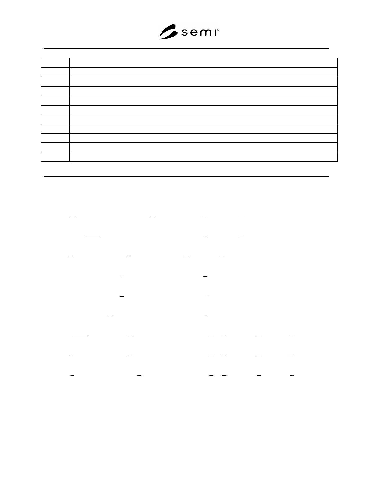
Table 1 Module Footprint Variables
Table 2 Definition of Module FootprintVariables
Figure 1 Radial Cluster Tool Module Footprint
SEMI E26-92 © SEMI 1992, 2004 2
Table 1 Modular Footprint Variables
L Transport module side length
(alpha) Angle subtended by a side of the transport module at the common point (see Section 3.1)
a
Half-minimum separation of adjacent module footprints
A
R
Half-width of reach area within the restricted area
A
M
Half-width of maintenance access area within the restricted area
W1 Module footprint primary width
W2 Module footprint secondary width
X1 Minimum distance to the interface plane for the module footprint primary width
X2 Maximum distance to the interface plane for the module footprint primary width
X3 Minimum distance to the interface plane for the module footprint secondary width
X4 Maximum distance to the interface plane for the module footprint secondary width
Table 2 Definition of Module Footprint Variables (Units are in mm)
420.0 L
2
90sin 420.0)-L(0.720
2
1
A
R
or
2
cos0.210
2
L
0.360
2
0.195
AA
RM
or
2
cos0.210
2
L
5.457
2
90sin)0.400L(
2
1
a
or
2
cos0.200
2
L
0.400
2
90cos320.02W1
or
0.400
2
sin0.640
W1
2
90cos0.27022W
or
0.400
2
sin0.1180
2
90sin0.3201X
or
2
cos0.320
X1
2
90seca
2
720.0
X2
or
2
cos0.590
2
cot0.200
2
L
2
cosec 0.360
X2
2
90tanW1W2
2
1
X3
or
2
cos0.590
2
cot0.200
2
L
2
cosec 0.360
X5
2
90sec0.7200.915
2
1
4X
or
2
cos0.590
2
cot0.200
2
L
2
cosec 7.545