semi合集-English.pdf - 第3910页
SEMI F31-0698 © SEMI 1998 4 7.2 Sour ce — The source of all flu i d s for incoming Bulk Chemical Distribution Systems is a container suitable for holding reactiv e che micals in a size 55 gallo ns or great er, which ma y…
SEMI F31-0698 © SEMI 19983
incorporates all of the physical activities and testing
parameters and establishes check points for approvals at
each stage.
6.3 Acceptance Tests — Acceptance tests are
conducted on each subsystem or system produced. They
are the basis for acceptance or rejection by the
purchaser.
6.3.1 Acceptance testing may include performance
demonstrations, demonstration of reliability criteria,
and achievement of purity standards. Safety
considerations are addressed elsewhere.
6.4 Qualification Testing — Qualification testing is
performed on the liquid chemicals being transported
through each chemical piping subsystem.
6.4.1 Qualification testing may include tests for trace
metals, anions, particles, and total organic carbon.
Assay analysis is recommended for blending or dilution
operations.
6.5 Chemical Specifications — Particulate BCD
Systems are specified as to the level of impurities at the
point of use as compared to the quality of the incoming
chemical. Impurities in the chemical are generally
specified in terms of particles per ml; metallic
impurities are specified for each element and for total
adders; and organic impurities are specified for total
added.
7 Basic Design Elements
7.1 General — Each Bulk Chemical Distribution
System contains certain basic components and a variety
of design options to meet particular customer and
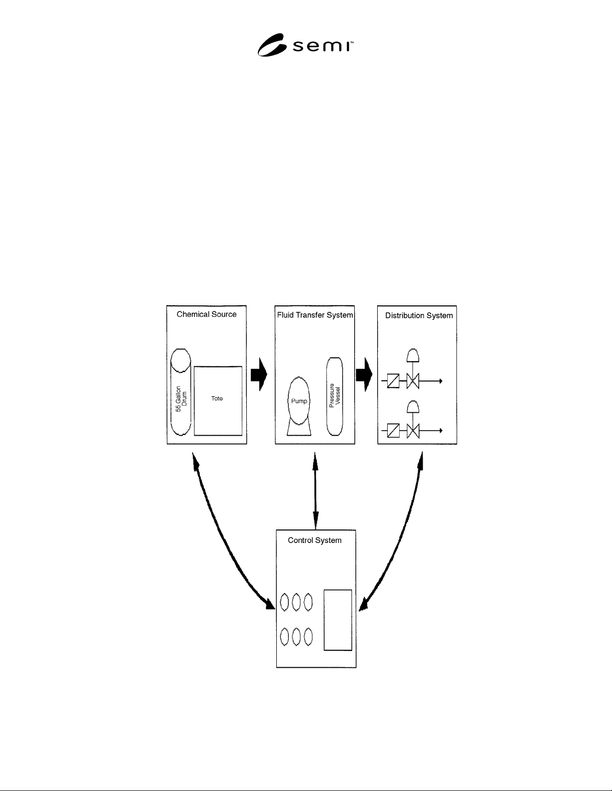
facility needs. A simple example system is shown in
Figure 1.
Figure 1
Schematic of Basic Bulk Chemical Distribution System

SEMI F31-0698 © SEMI 1998 4
7.2 Source — The source of all fluids for incoming
Bulk Chemical Distribution Systems is a container
suitable for holding reactive chemicals in a size 55
gallons or greater, which may include drums, totes,
vessels, or ISO containers.
7.3 Fluid Transfer — Fluids in the Bulk Chemical
Distribution Systems are transported through pipes
using either a pumping system, a pressure differential
system, or some combination of the two types of basic
systems. All fluids are transported in secondary
containment piping systems for safety reasons.
7.4 Distribution — The transfer is made from the
source by means of certain types of mechanisms,
usually through one or more valve manifold boxes, that
direct the fluid to a point of use, to subordinate levels of
distribution, and/or to a day tank.
7.5 Control Systems — Manual and/or automated
mechanical, pneumatic, hydraulic, optical, and
electronic systems control the movement of the liquids.
This includes the volume, flow rate, pressure, start-up,
and shut-off.
8 Optional Design Features
8.1 Polishing — BCD Systems ma y be designed with
the possibility of chemical recirculation (1) from the
incoming source and back, to polish the incoming
chemical; (2) from the day tank and back for further
polishing or timed recirculation if activity is limited;
and (3) fabwide in continuous recirculation.
8.2 Filtration — Chemicals in the system may be
recirculated through filters placed on-line in the system.
The relevant design issues include types of filters,
efficiency, useful lifetime, qualification, filter bleed,
removal, and replacement.
8.3 Day Tank — The vessel that generally stores a
limited amount of chemical volume generally
equivalent to that used in about one day of operation.
This holding vessel usually stores prefiltered chemical
before it is transferred to the manufacturing process.
8.4 Blending — Certain chemicals in distribution are
blended together for use in the semiconductor
manufacturing process. For example, Buffered Oxide
Etchant is a blend of Hydrofluoric Acid and
Ammonium Fluoride and may be sourced as two
separate chemicals and blended together in the correct
concentrations within the BCD Systems.
8.5 Dilution — Certain chemicals used in the
semiconductor manufacturing process require various
concentrations, depending on the process used at a
particular point in the system. For example, 49%
Hydrofluoric Acid is brought in as the source chemical
and then mixed with DIW in a blend unit to achieve
various concentrations of 10:1, 100:1, etc., depending
on the requirements of the manufacturing process.
8.6 Automated Control Systems — Electronic systems
may be programmed to control system parameters such
as volume, pressure, fill rate, flow, drain times,
maintenance diagnostics, purge cycles, recirculation,
and bypass.
8.7 Sampling Ports — Sampling ports may be
incorporated into the system to facilitate chemical
sampling for qualification and monitoring programs.
8.8 On-Site Chemical Generation — Liquid
chemicals, such as Ammonium Hydroxide, may be
generated on-site at the required concentration from a
clean Ammonia gas source and DIW to the required
concentration. Generally, this activity is done in a
location apart from the dispense room. The resulting
chemical is used as a source for the distribution system.
8.9 Reprocessing — Integrated with the general
chemical distribution system may be a chemical
reprocessing unit which purifies or recycles a chemical
such as sulfuric acid, isopropanol, or hydrofluoric acid.
Such a system enables the chemical to reenter the
system as a clean source of material for manufacturing
processing.
8.10 Stabilized Filtration — Some systems include a
design feature that provides for the continuous flow of
chemical over filters to minimize shocking and
pulsating of the filters.
8.11 Surge Suppression — Some systems include a
device or in-line chamber that minimizes hydraulic
forces caused by a pump. This option may also be
referred to as pulsation dampener.
9 Monitoring and Maintenance of Systems
9.1 General Considerations — Bulk Chemical
Distribution Systems may require a significant level of
maintenance and monitoring to determine that
specifications and performance are initially and
continually met.
9.2 Functional Management System — The entire
dispense system can be monitored by means of
PC/PLC/ or any hybrid system, recording events as they
occur and alerting operators as necessary to take
corrective action. Monitoring systems may include a
variety of operational parameters:
9.2.1 on-line real-time monitoring of all chemical
dispense units
9.2.2 status of components and subsystems
9.2.3 events logging

SEMI F31-0698 © SEMI 19985
9.2.4 data management
9.2.5 reliability parameters, including lead detection
9.2.6 chemical usage
9.2.7 display of dispense systems
9.2.8 communication gateway to the factory alarm
system
9.2.9 on-line documentation
9.2.10 predictive maintenance planning
9.2.11 chemical interruptions to the fab by location,
indicating location of fault.
9.3 Maintenance — Maintenance of the BCD Systems
includes routine and preventative maintenance of
pumps, filters, valves, and other components.
9.4 Monitoring Programs — Each BCD System
should be monitored to determine if liquid chemicals
delivered to the tools for use in the manufacturing
process continually meet specifications and are within
initial and ongoing established process control limits.
9.4.1 Monitoring programs may include periodic
testing of the liquid chemicals to determine levels of
particles, trace metals assay, and other parameters of
interest. Certain tests may be done continuously on-line
(e.g., particles), and other analytical tests are performed
periodically from samples taken at various points in the
system.
NOTICE: These standards do not purport to address
safety issues, if any, associated with their use. It is the
responsibility of the user of these standards to establish
appropriate safety and health practices and determine
the applicability of regulatory limitations prior to use.
SEMI makes no warranties or representations as to the
suitability of the standards set forth herein for any
particular application. The determination of the
suitability of the standard is solely the responsibility of
the user. Users are cautioned to refer to manufacturer’s
instructions, product labels, product data sheets, and
other relevant literature respecting any materials
mentioned herein. These standards are subject to
change without notice.
The user’s attention is called to the possibility that
compliance with this standard may require use of
copyrighted material or of an invention covered by
patent rights. By publication of this standard, SEMI
takes no position respecting the validity of any patent
rights or copyrights asserted in connection with any
item mentioned in this standard. Users of this standard
are expressly advised that determination of any such
patent rights or copyrights, and the risk of infringement
of such rights, are entirely their own responsibility.
Copyright by SEMI® (Semiconductor Equipment and Materials
International), 3081 Zanker Road, San Jose, CA 95134. Reproduction o
f
the contents in whole or in part is forbidden without express written
consent of SEMI.