semi合集-English.pdf - 第6416页
SEMI G75.2-069 8 © SEMI 1998 3 Figure 5 Typical Taped 4 0 Pin DIP Leadfra m e Table 2 Relevant Information for 40 Pin DIP Lead frame Leadframe Attrib ute Specification Leadframe t hickness 0.25 mm Leadframe material Allo…
SEMI G75.2-0698 © SEMI 1998 2
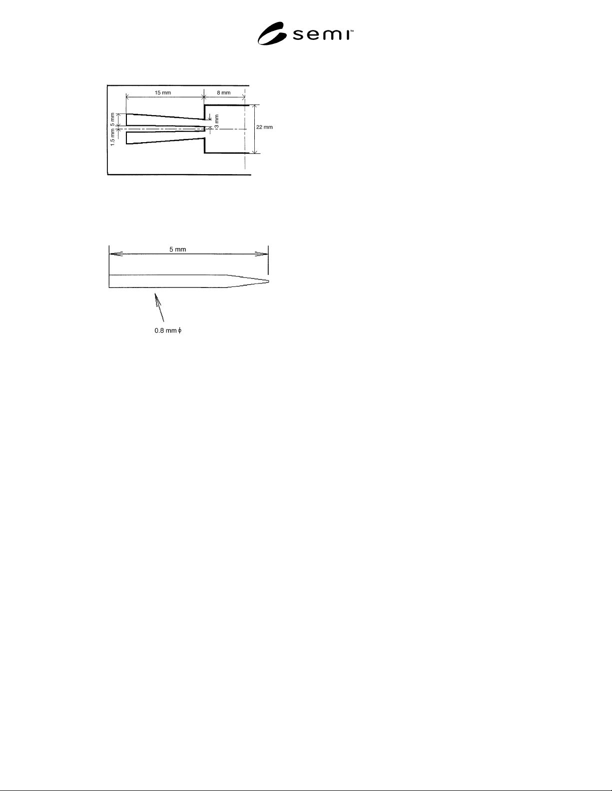
Figure 3
The Dimension of the Table
Figure 4
Example of Push-Down Probe
(40 Pin DIP Leadframe)
3 Test Condition
3.1 Adhesion testing shall be carried out at the
following ambient conditions:
Temperature — 23°C ± 5°C
Humidity — 50 ± 5% RH
4 Sampling
4.1 The sampling is one sample per one lot. The
vendor must report the definition of lot, if the customer
requires it.
5 Preparation of Specimens
5.1 Leadframe Manufacturers
5.1.1 Leadframes shall be taped using conditions for
temperature, pressure, and dwell-time agreed upon
between vendor and customer.
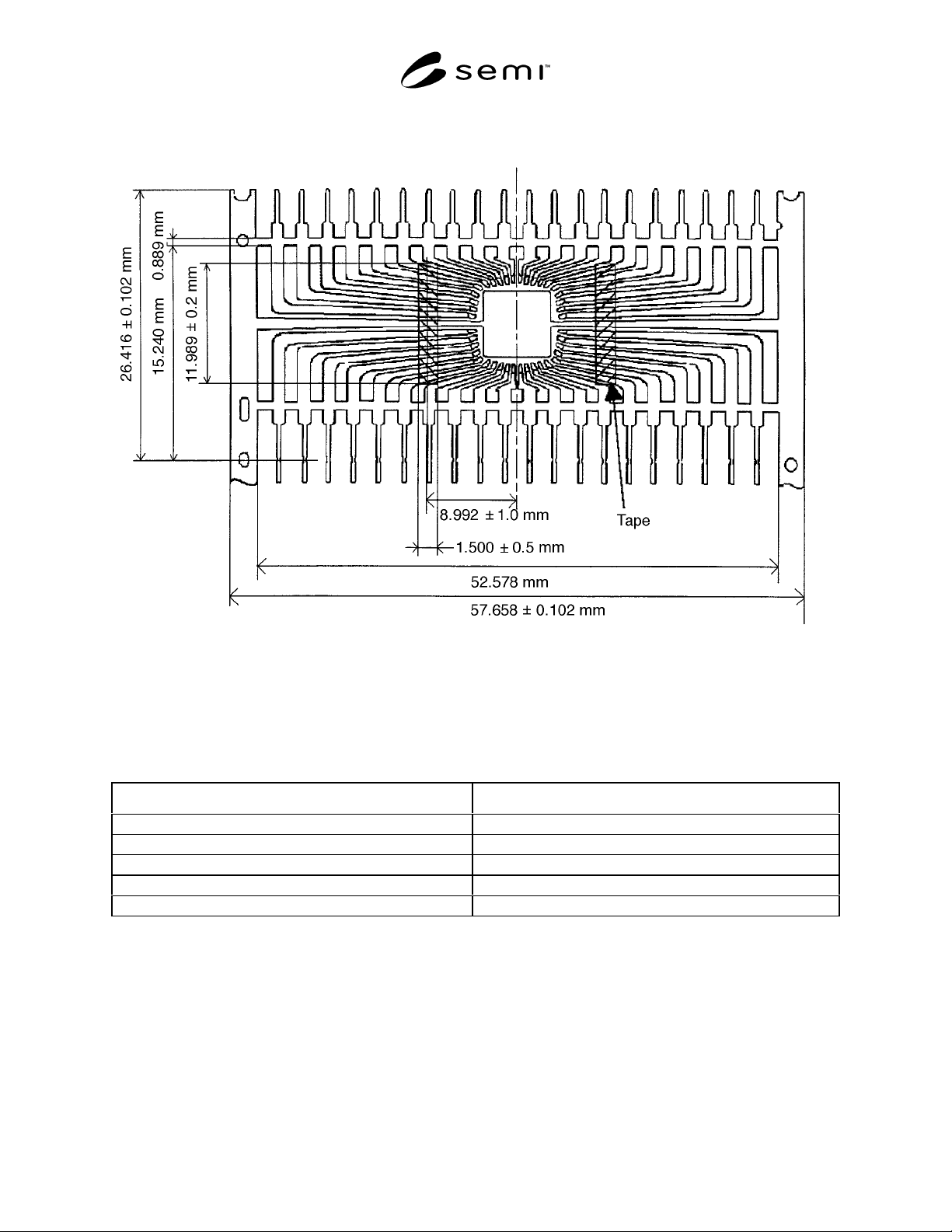
NOTE: A typical taped 40 pins DIP leadframe is shown in
Figure 5, and relevant information for this frame is shown in
Table 2.
SEMI G75.2-0698 © SEMI 19983
Figure 5
Typical Taped 40 Pin DIP Leadframe
Table 2 Relevant Information for 40 Pin DIP Leadframe
Leadframe Attribute Specification
Leadframe thickness 0.25 mm
Leadframe material Alloy 42
Leadframe manufacturing process Stamping
Plating None/Silver/Others
Surface treatment To be agreed upon between vendor and customer.
NOTE: The surface state of Alloy 42 is stable compared with Cu alloy which is oxidized easily.
6 Procedure
Hot adhesive strength at 250°C should be measured on the heater block with 60 ± 10 seconds.
6.1 Pull-Up Procedure
6.1.1 Set the tensile tester in the up-mode, and adjust the rate to 100 mm/minute.
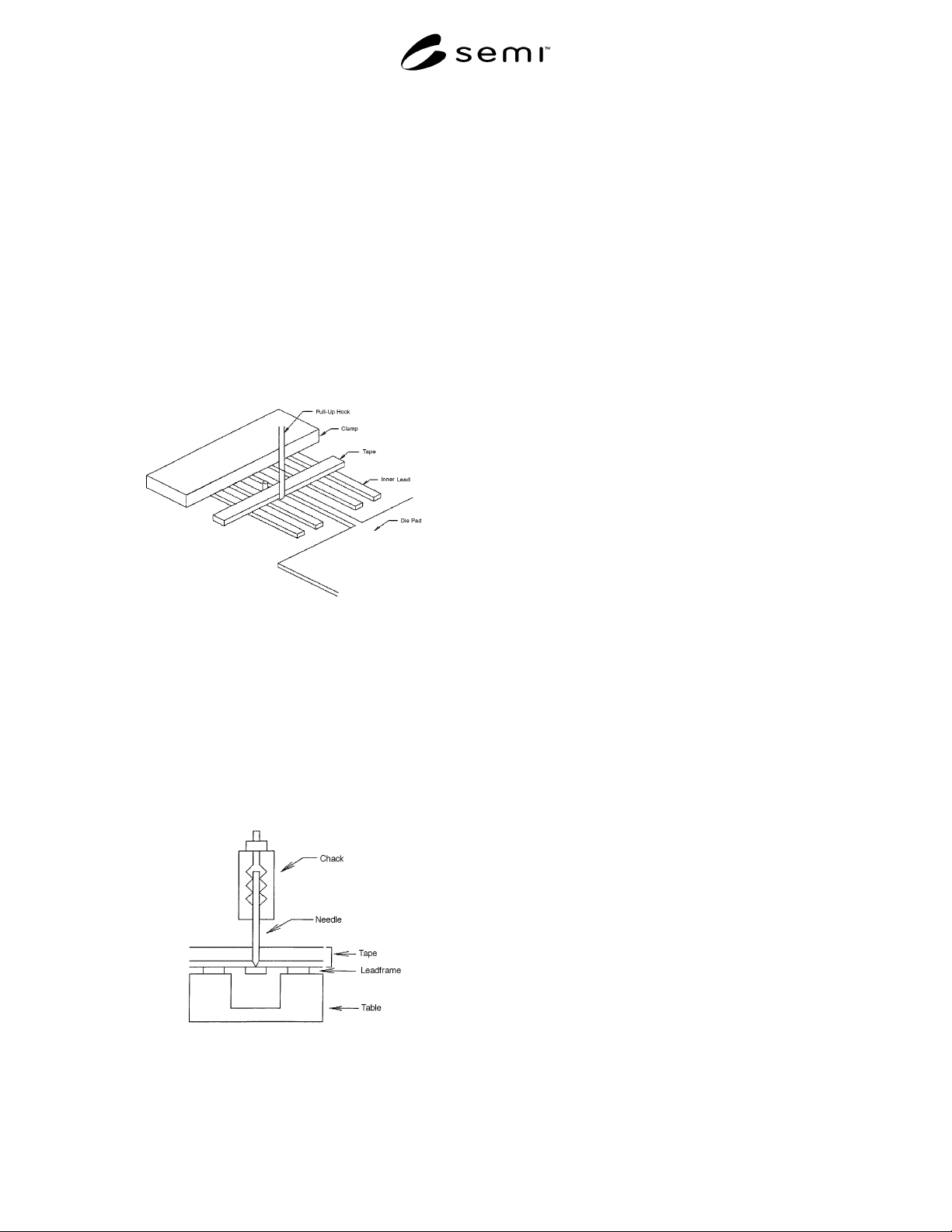
6.1.2 Place the leadframe under the clamp as shown in Figure 6.
SEMI G75.2-0698 © SEMI 1998 4
6.1.3 Position the hook under the tape between the tie
bar and its neighboring inner lead as shown in Figure 6.
Similar leads and hook position shall be selected for
other types of leadframes.
6.1.4 Adjust the hook position until it just touches the
tape and initiate the tensile tester in the up-mode.
Record the strength to break the adhesion between the
lead and the tape.
6.1.5 Repeat the test for each leadframe in the
samples.
6.1.6 Calculation
6.1.6.1 Discard the maximum and minimum values
recorded, and average the remainder.
Figure 6
Measurement of Pull-Up Strength
6.2 Push-Down Procedure
6.2.1 Set the tensile tester in the down-mode, and
adjust the rate to 100 mm/minute.
6.2.2 Place the leadframe on the table as shown in
Figures 7 and 8.
6.2.3 Position the probe at Point A over the selected
inner lead as shown in Figure 9.
Figure 7
Measurement of Push-Down Strength
(Cross-Section)