semi合集-English.pdf - 第1521页
SEMI E32-0997 © SEMI 1994 , 1997 16 4.2.3 At omic Transfer State Model — W h e n a transfer job becomes active, it creates a queue of atomic transfers for each port (see Transition 2 of the transfer job state m odel). Th…
SEMI E32-0997 © SEMI 1994, 199715
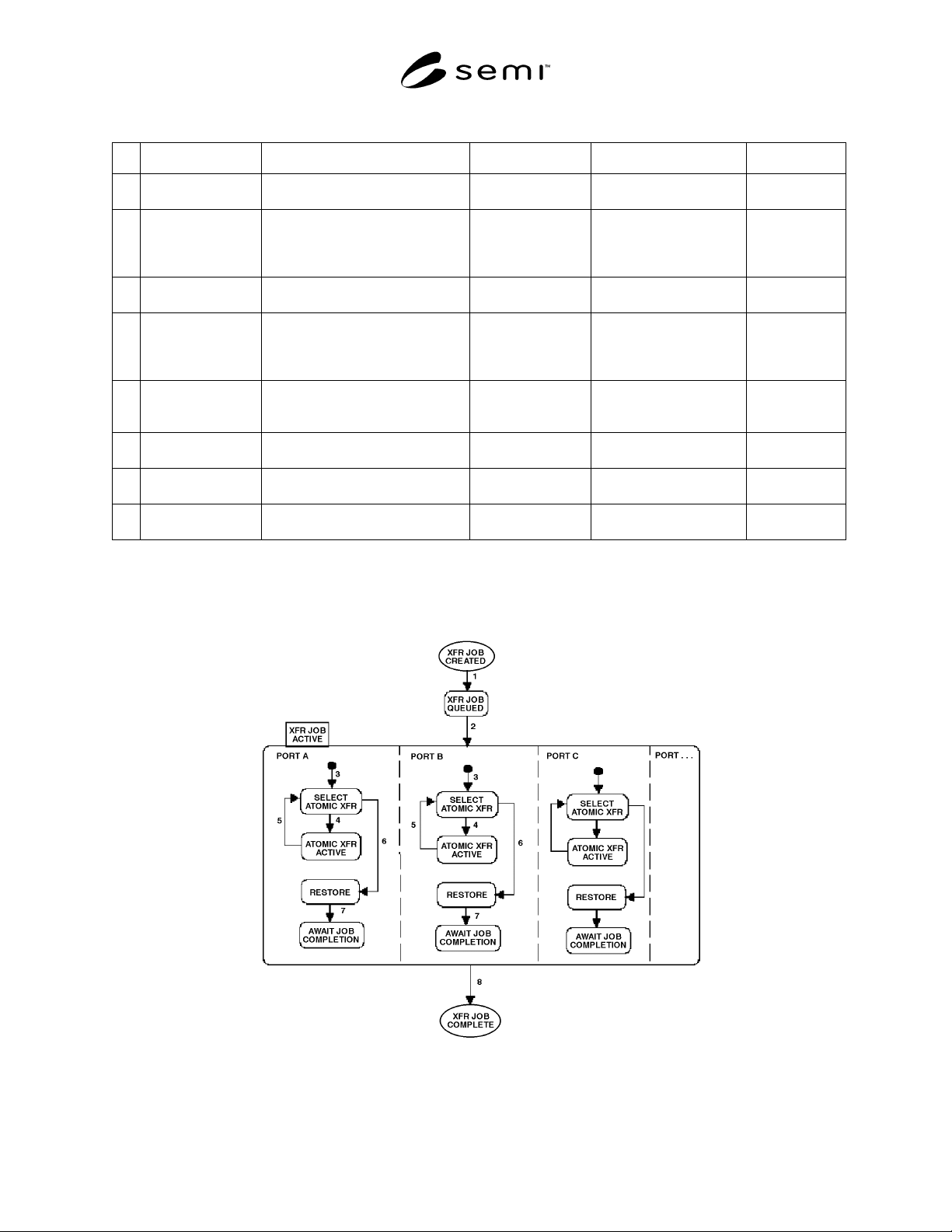
Table 4.1 Transfer Job State Transition Table
# Current State Trigger New State Action(s) Comment
1 (Transfer Job
Created)
The equipment accepts a Transfer
Job from the host.
TRANSFER JOB
QUEUED
Place the transfer job in
the queue.
None.
2 TRANSFER JOB
QUEUED
Necessary material locations have
been allocated to transfer job and
any equipment-specific
prerequisites met.
TRANSFER JOB
ACTIVE
Remove the transfer job
from the queue. Send
“Transfer Job Started”
message.
None.
3 Any... Default entry into the PORT A (or
PORT B, etc.) state
SELECT ATOMIC
TRANSFER
All atomic transfers are
queued (by port).
None.
4 SELECT ATOMIC
TRANSFER
Atomic transfer selected for
execution on this port.
ATOMIC
TRANSFER
ACTIVE
Cause selected atomic
transfer to transition from
queued to setup.
See Sec. 4.2.3
for the atomic
transfer state
model.
5ATOMIC
TRANSFER
ACTIVE
Atomic transfer complete event
from the atomic transfer state
model.
SELECT ATOMIC
TRANSFER
None. None.
6 SELECT ATOMIC
TRANSFER
No atomic transfers remain for this
port.
RESTORE None. None.
7 RESTORE Port returned to desired idle
conditions.
AWAIT JOB
COMPLETION
None. None.
8 TRANSFER JOB
ACTIVE
All atomic transfers for the transfer
job are completed.
(Transfer Job
Complete)
Send “Transfer Job
Complete” message.
None.
Figure 4.5 begins with the model in Figure 4.4 and is expanded to cover a transfer job with multiple ports. Each
transfer job, as seen by the equipment, may include from one port to the total number of ports on the equipment.
Figure 4.5
Transfer Job State Model for Multiple Ports
SEMI E32-0997 © SEMI 1994, 1997 16
4.2.3 Atomic Transfer State Model — When a transfer
job becomes active, it creates a queue of atomic
transfers for each port (see Transition 2 of the transfer
job state model). These atomic transfers are executed as
described in the transfer job state model above. This
section describes the behavior of the atomic transfer as
it is created, executed, and finally deleted.
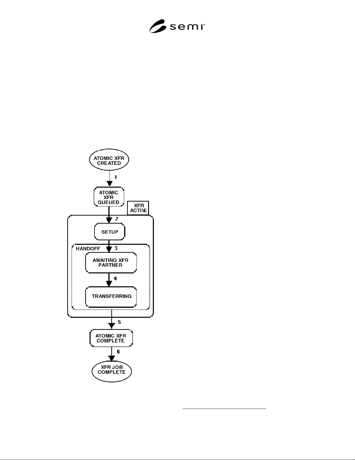
Figure 4.6 shows the state model for an atomic transfer
as it moves through its life cycle. Each atomic transfer
of an active transfer job is represented by a separate
copy of this state model. These state models are not
substates of the transfer job state model. Rather,
transfer job and atomic transfers are separate entities
which interact.
Figure 4.6
Atomic Transfer State Diagram
The definitions for the states and state transitions
follow.
ATOMIC TRANSFER QUEUED
In this state, the atomic transfer is awaiting its turn to
execute at the port.
TRANSFER ACTIVE
In this state, the transfer job has activated this atomic
transfer. The atomic transfer is performed entirely
within this state. The substates of TRANSFER
ACTIVE are SETUP and HANDOFF.
The TRANSFER ACTIVE state in this model
corresponds to the ATOMIC TRANSFER ACTIVE
state in the transfer job state model. Thus, when the
transfer job activates an atomic transfer on a port, both
state models shall be in the (ATOMIC) TRANSFER
ACTIVE state during the atomic transfer. This applies
only to the specific atomic transfer being performed.
SETUP
While in the SETUP substate, the equipment performs
any pre–transfer setup operations necessary for the
current atomic transfer. These operations might include
(but are not limited to) opening doors, unclamping
carriers, and homing elevators. For transfer agents, it is
reasonable to include as part of the setup such actions
as a transfer agent moving into position near a specified
process equipment.
The setup and restore
8
operations are expected to be
“goal oriented,” that is, oriented toward satisfying
specific conditions (e.g., states such as “door open”).
They should not depend on a fixed sequence of actions
such as “initiate the door opening mechanism.” Thus, a
port left in a post–transfer condition from a previous
atomic transfer would still be able to prepare properly
for the next.
If no setup time is required for the transfer, this state
may be exited immediately. This is the case for a static
port since it can perform no physical actions related to
setup.
HANDOFF
The equipment is committed to the transfer when no
setup operations remain and the port is capable of
performing the transfer. Entry into the HANDOFF state
indicates that the port shall take no further action
without the (expressed or implicit) cooperation of its
transfer partner. Both transfer partners shall be in the
HANDOFF state when the atomic transfer begins.
8 Restore is described in Section 4.2.2.

SEMI E32-0997 © SEMI 1994, 199717
The HANDOFF substate is divided into two further
substates: AWAITING TRANSFER PARTNER AND
TRANSFERRING.
NOTE: If one transfer partner has not yet reached the
HANDOFF substate when the other begins the transfer,
interference could occur on the part of the uncommitted
partner, with potential to damage equipment or
material. The micro level Transfer Ready exchange will
help prevent this (see Section 5 below).
AWAITING TRANSFER PARTNER
Once the port is ready for the transfer, the AWAITING
TRANSFER PARTNER substate is entered. The port
shall remain in this state until its transfer partner is
ready.
TRANSFERRING
In this state, the physical handoff portion of the atomic
transfer is in progress. Most micro level coordination
occurs while the transfer partners are both in the
TRANSFERRING state.
ATOMIC TRANSFER COMPLETE
In this state, the atomic transfer has completed and is
awaiting the completion of the job. Upon entry to this
state, the equipment shall release (deallocate) the port
resources used for this atomic transfer. It shall also
deallocate any material location used by this atomic
transfer that is not needed by any further atomic
transfer in this transfer job. This state exists primarily to
allow the host to poll for current status of the individual
atomic transfers (there is no status if the atomic transfer
no longer exists).
The following transition table defines the transitions
between states for the atomic transfer state model. It
applies to Figure 4.6.
Table 4.2 Atomic Transfer State Transition Table
# Current State Trigger New State Action(s) Comment
1 (Atomic Transfer
Created)
The parent transfer job
becomes active
(see Table 4.1).
ATOMIC
TRANSFER
QUEUED
None. None.
2 ATOMIC TRANSFER
QUEUED
The parent transfer job
selects this atomic transfer
as next for a port and
transitions to ATOMIC
TRANSFER ACTIVE.
SETUP None. None.
3 SETUP All preparation for this
atomic transfer is complete.
AWAITING
TRANSFER
PARTNER
None. “Committed To Transfer” event
occurs. See micro level Transfer
Ready message.
4AWAITING
TRANSFER
PARTNER
Transfer partner is ready
for transfer (see micro
level).
TRANSFERRING None. “Atomic Transfer Started” event
occurs. This transition might not
occur for a static port.
5 HANDOFF The atomic transfer is
completed.
ATOMIC
TRANSFER
COMPLETE
None. The “Atomic Transfer Complete”
event occurs. This transition will
occur after the appearance or
removal of the material at the port.
See the micro level Transfer
Verify message.
6 ATOMIC TRANSFER
COMPLETE
The parent transfer job is
completed.
(Transfer Job
complete)
The atomic
transfer is
deleted.
After this transition, the
equipment maintains no status of
the atomic transition.