semi合集-English.pdf - 第2110页
SEMI E54.14-0305 © SEMI 2005 4 5.3 Termin ology Ma pping 5.3.1 As this standard defines the mapping of CDM data structure and behavi or over a netwo rk it makes use of ma ny of the term s in SEMI E54.1. Table 1 provides …

SEMI E54.14-0305 © SEMI 2005 3
5.1.2 AREP — Application Reference Endpoint
5.1.3 ASE — Application Service Element
5.1.4 CDM — Common Device Model
5.1.5 DCE — Distributed Computing Environment
5.1.6 DCP — Discovery and Configuration Protocol
5.1.7 DHCP — Dynamic Host Configuration Protocol
5.1.8 DM — Device Manager
5.1.9 GSD — Generic station description
5.1.10 IM — Identification and Maintenance
5.1.11 IO — Input Output
5.1.12 IP — Internet Protocol
5.1.13 NCS — Network Communication Standard
5.1.14 OSI — Basic Reference Model for Open Systems Interconnection (ISO 7498)
5.1.15 PDU — Protocol Data Unit
5.1.16 PHY — Physical Layer
5.1.17 RPC — Remote Procedure Call
5.1.18 SAC — Sensor, actor, controller (object)
5.1.19 SAN — Sensor/actor network
5.1.20 SAP — Service Access Point
5.1.21 SDM — Specific Device Model
5.1.22 UDP — User Datagram Protocol
5.2 Terminology Defined in Sensor/Actuator Network Common Device Model (SEMI E54.1)
5.2.1 attribute
5.2.2 behavior
5.2.3 byte
5.2.4
common device model
5.2.5 device
5.2.6 Device Manager (DM) Object
5.2.7 device model
5.2.8 instance
5.2.9 network communication standard
5.2.10 object
5.2.11 Sensor, Actuator and Controller (SAC) Object
5.2.12 service
5.2.13 specific device model
5.2.14 state diagram
SEMI E54.14-0305 © SEMI 2005 4
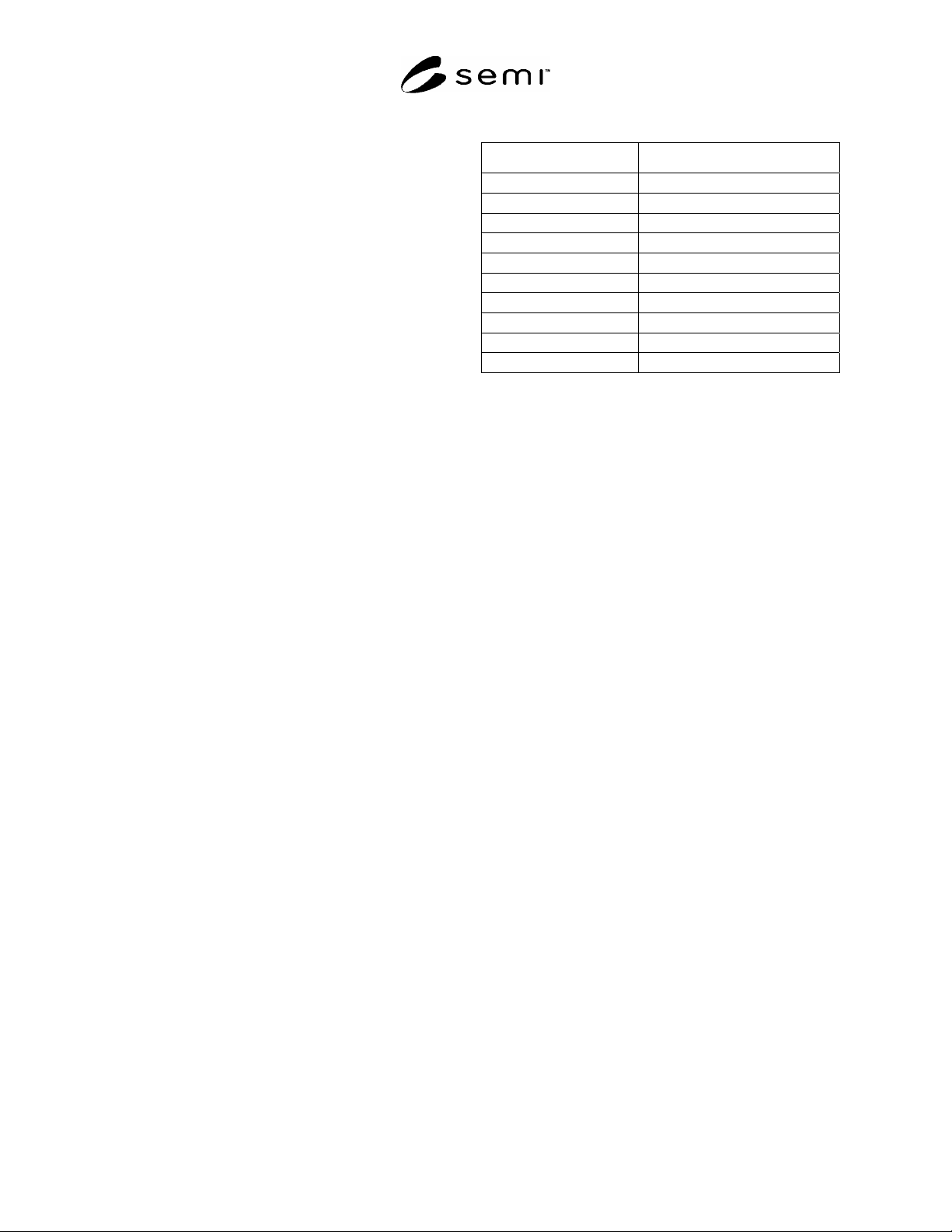
5.3 Terminology Mapping
5.3.1 As this standard defines the mapping of CDM
data structure and behavior over a network it makes
use of many of the terms in SEMI E54.1. Table 1
provides a mapping of fundamental terminology of
the CDM document into this document which uses the
terminology of PROFINET IO.
5.4 PROFINET Specific Definitions
5.4.1 Context Management — network-accessible
information (communication objects) that supports
managing the operation of the system, including the
application layer.
NOTE 1: Managing includes functions such as controlling,
monitoring, and diagnosing.
5.4.2 Device Data Base — an electronic file that provides a clear and comprehensive description of the
characteristics of a device type in a precisely defined format. Also called a GSD File.
5.4.3 Device Profile — a Device Data Base Sheet, which specifies the characteristic features of a device, and a
GSD File.
5.4.4 channel — single physical or logical link of an input or output application object of a server to the process.
5.4.5 channel related diagnosis — information concerning a specific element of an input or output application
object, provided for maintenance purposes.
5.4.6 diagnosis data object — object(s) which contains diagnosis information referenced by
device/slot/subslot/diagnosis identifier.
5.4.7 GSD File — see Device Data Base.
5.4.8 Index — address of a record data object.
5.4.9 IO Controller — a device that manages its assigned IO Devices and handles user data exchange; usually a
programmable controller.
5.4.10 IO data object — object designated to be transferred cyclically for the purpose of processing and referenced
by device/slot/Subslot.
5.4.11 IO Device — a device that is configured and managed by IO Controllers and IO Supervisors; an IO Device
initiates no unsolicited communications.
5.4.12 IO Supervisor — a device that interacts as a configuration or diagnostic tool; usually a programming device.
5.4.13 module — hardware or logical component of a physical device.
5.4.14 provider — node or source sending data to one or many consumers.
5.4.15 record data object — object(s) which are already pre-processed and transferred acyclically for the purpose
of information or further processing and referenced by device/slot/subslot/index.
5.4.16 resource — processing or information capability.
5.4.17 server — a) role of an AREP in which it returns a confirmed service response APDU to the client that
initiated the request — b) object which provides services to another (client) object.
5.4.18 service — operation or function that an object and/or object class performs upon request from another object
and/or object class.
5.4.19 Service Access Point — an addressable location in a device for the directing of service requests.
5.4.20 slot — address of a structural unit within an IO device.
Table 1 Mapping of CDM to NCS Terminology
CDM Term NCS Equivalent
Device IO Device
Object =(with ASE as class specification)
Instance =
Attribute =
Behavior =
Service =
State Diagram Protocol Machine, State Machine
Byte =, Unsigned8
Nibble Specific field coding
Character String Visible String
SEMI E54.14-0305 © SEMI 2005 5
NOTE 2: Within a modular device, a slot typically addresses a physical module. Within compact devices, a slot typically
addresses a logical function or virtual module.
5.4.21 slot related diagnosis — information dedicated to modules for maintenance purpose.
5.4.22 submodule — hardware or logical component of a module.
5.4.23 subslot — address of a structural unit within a slot.
NOTE 3: A subslot may address a physical interface for submodules within a module. Generally, a subslot is a second level to
structure data within a device.
5.4.24 vendor ident number — central administrative number assigned by the PNO.
6 Communication Protocol High Level Structure
6.1 The PROFINET IO protocol constitutes a collapsed form of the OSI seven layer architecture. PROFINET IO
uses physical, data link, network, transport, and application layers of the Reference Model. For real time
communication a three layer approach with physical, data link and application is specified. This section has been
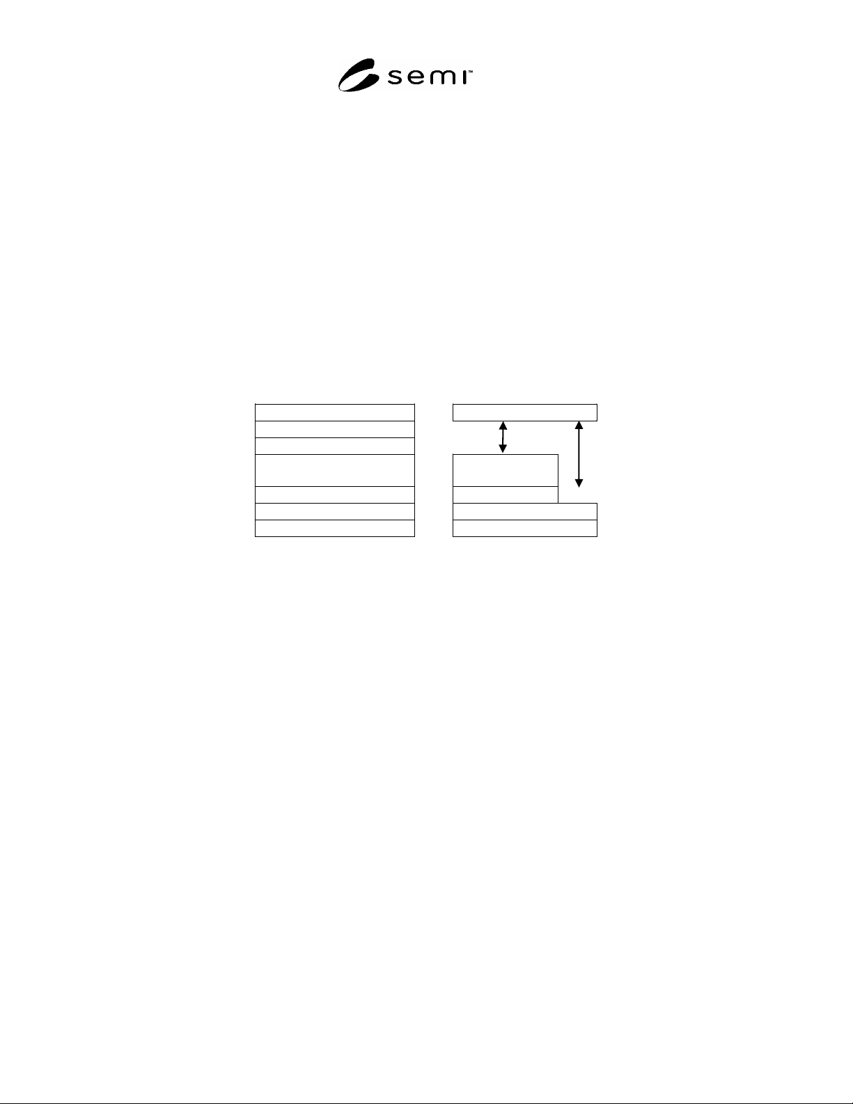
formatted to be aligned with the Basic Reference Model for OSI. Figure 1 gives an overview of the architecture.
OSI Reference Model NCS Model
Application Layer Application Layer
Presentation Layer
Session Layer
Transport Layer Transport
Layer
Network Layer Network Layer
Data Link Layer Data Link Layer
Physical Layer Physical Layer
Figure 1
Layering of PROFINET in Relation to OSI
6.2 General Behavior
6.2.1 In a typical remote I/O configuration, single IO controller architectures are used to optimize response times.
In lower speed applications, multi IO controller architectures are also possible.
6.2.2 Message transfer is organized in cycles. A message cycle mainly consists of a set of Output Data Frames of
the IO controller and a set of Input Data Frames of several IO devices. Every Output Data Frame is associated to an
Input Data Frame. The monitoring of an IO application relationship is done by the receiver of that frames.
6.2.3 A brief description of the PROFINET protocol as it relates to the ISO 7498 OSI model follows in the sections
below. For protocol efficiency, PROFINET does not define layers 3 to 7 for cyclic IO data transfer and alarms.
Layer 7 is the interface between the Application Process and the communication stack.
NOTE 4: The information contained in this section is for reference only. It in no way represents specifications for PROFINET.
See related documentation for these specifications.
6.3 Physical Layer — Layer 1
6.3.1 The Physical Layer of IEEE 802.3 is adopted. There are two recommendations specified for the Physical
Layer (PHY): twisted pair (100 Base TX) and optical (100 Base FX) in PROFINET. See IEEE 802.3 standard for
more information about these options. More Details are specified in the PROFINET Installation Guideline. If an
accepted physical standard other than IEEE 802.3 is being used it has be clearly specified in the product
documentation.