semi合集-English.pdf - 第4517页
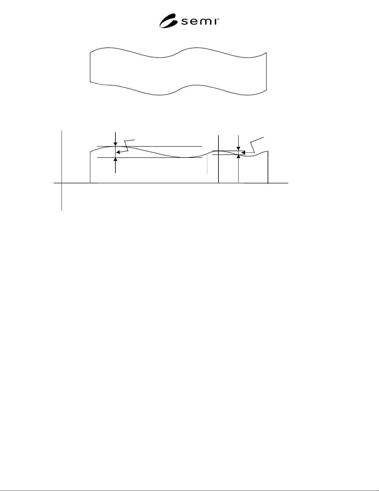
SEMI D24-0200 © SEM I 2000 7 (Back S urface Unconstrained ) Free State X 0 Z (Back S urface Constrained ) Ideal Chu cked State Exposure Site Local Thi ckness Varia tion Total Thickness Varia tion Figure 6 Total Thic knes…
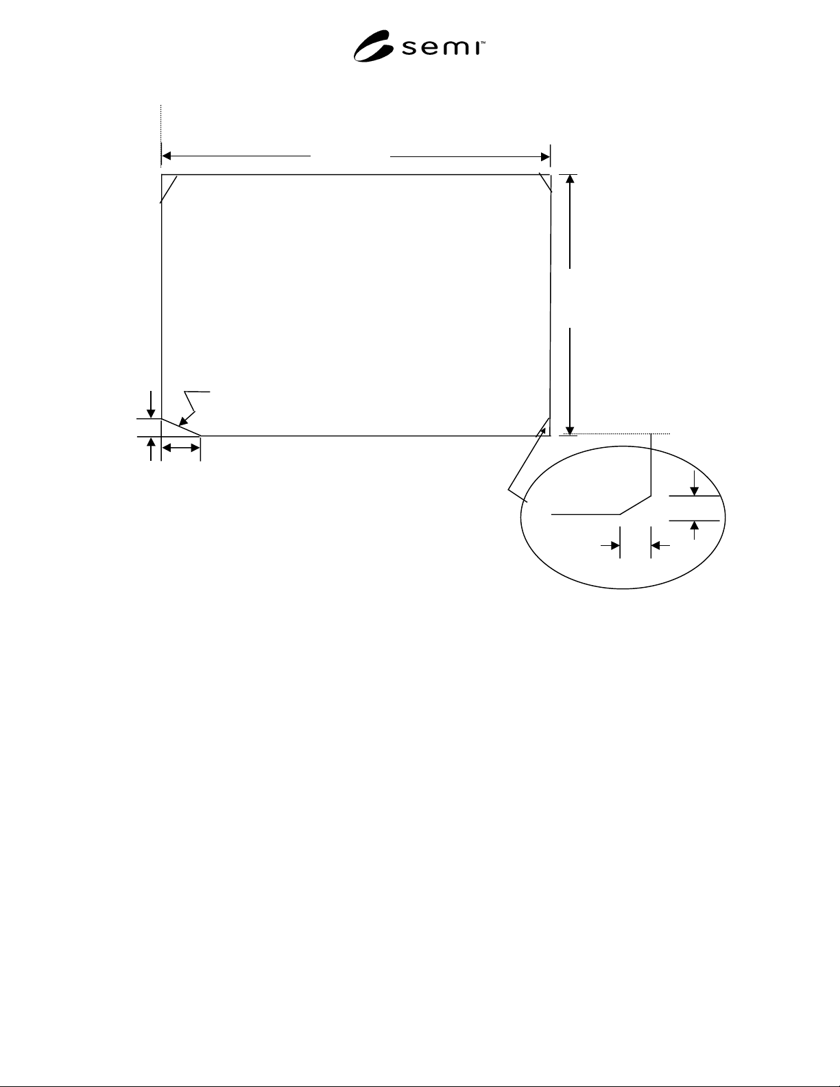
SEMI D24-0200 © SEMI 2000 6
C
2x
(Pattern Surface)
Length(L)
Width(W)
Orientation
(LRE)
(SRE)
Corner Cut
(3 places)
Y-Axis
X-Axis
C1x
C1y
C2x
C2y
Figure 5
Orientation Corner and Corner Cuts
SEMI D24-0200 © SEMI 20007
(Back Surface Unconstrained)
Free State
X
0
Z
(Back Surface Constrained)
Ideal Chucked State
Exposure
Site
Local Thickness
Variation
Total Thickness
Variation
Figure 6
Total Thickness Variation and Local Thickness Variation
NOTICE: SEMI makes no warranties or representations as to the suitability of the standard set forth herein for any
particular application. The determination of the suitability of the standard is solely the responsibility of the user.
Users are cautioned to refer to manufacturer’s instructions, product labels, product data sheets, and other relevant
literature respecting any materials mentioned herein. These standards are subject to change without notice.
The user’s attention is called to the possibility that compliance with this standard may require use of copyrighted
material or of an invention covered by patent rights. By publication of this standard, SEMI takes no position
respecting the validity of any patent rights or copyrights asserted in connection with any item mentioned in this
standard. Users of this standard are expressly advised that determination of any such patent rights or copyrights, and
the risk of infringement of such rights, are entirely their own responsibility.
Copyright by SEMI® (Semiconductor Equipment and Materials
International), 3081 Zanker Road, San Jose, CA 95134. Reproduction o
f
the contents in whole or in part is forbidden without express written
consent of SEMI.

SEMI D25-0600
E
© SEMI 2000, 2003 1
SEMI D25-0600
E
SPECIFICATION FOR FLAT PANEL DISPLAY SUBSTRATE SHIPPING
CASE
This specification was technically approved by the Global Flat Panel Display Committee and is the direct
responsibility of the Japanese Flat Panel Display Committee. Current edition approved by the Japanese
Regional Standards Committee on April 21, 2000. Initially available on SEMI OnLine May 2000; to be
published June 2000.
E
This document was editorially modified in October 2003 to correct general editorial errors. Changes were
made to Sections 3.2.2, 6.2.8.1, 6.2.9.1, and A3-1 (figure).
1 Purpose
1.1 This document provides the packing and shipping
specifications and/or guides for FPD glass substrates,
which are called fourth generation substrates (800 ×
950 × 0.7 mm or 800 × 950 × 1.1 mm).
1.2 The objective of this document is to provide cost-
effective packing and shipping in terms of packing
materials, storage, and shipping, while making sure that
packing meets the quality and automation requirements.
2 Scope
2.1 This document defines a specification for a full box
type shipping case (see Figure 2) to be used for packing
and shipping of 4
th
generation FPD glass substrates
from the manufacturer of the glass substrate to the user.
2.2 The application of this packing specification is
limited to the following four FPD glass substrates:
2.2.1 Bare glass substrates which can be used as array
substrates, and do not have film deposition.
2.2.2 Bare glass substrates which can be used as facing
substrates and color filter substrates, and do not have
film deposition.
2.2.3 Array substrates which do have film deposition.
2.2.4 Facing substrates and color filter substrates which
do have film deposition.
2.3 This standard does not purport to address safety
issues, if any, associated with its use. It is the
responsibility of the users of this standard to establish
appropriate safety and health practices and determine
the applicability of regulatory limitations prior to use.
3 Prerequisites and Limitations
3.1 This specification does not apply to:
3.1.1 cassettes used for intra/inter bay transfer inside
the user’s plant;
3.1.2 the semi-separating type the contact type packi-
ng method (see Figure 4) or the full corner supporter
type and the double side supporter type (see Figure 3)
3.2 The premise for glass substrates for this packing
specification is as follows.
3.2.1 Size
W (mm): Short Edge
L (mm): Long Edge
t (mm): Thickness
W = 800 mm W tolerance: see SEMI D24
L = 950 mm L tolerance: see SEMI D24
t = 1.1 t tolerance = see SEMI D24
t = 0.7 t tolerance = see SEMI D24
3.2.2 Squareness — see SEMI D24
3.2.3 Beveling — R beveling
3.2.4 Orientation Corner — see SEMI D24
3.2.5 Corner Cut — see SEMI D24
3.2.6 Edge Exclusion Area — see SEMI D24
3.2.7 Sag — In the event of the glass substrate being
placed horizontally on the support as shown in Figure 1,
sag is defined by h2 (two sides supported), and h4 (four
sides supported) (Unit = mm) (see Figure 1).
3.2.8 Density — Less than 2.8 g/cm
3
3.3 When the glass substrates are shipped, they shall be
loaded vertically.
3.4 When the glass substrates are shipped, a standard
sized pallet shall be used for efficient loading on the
truck platform or the floor of the container (see
Appendices 1 and 2). The standard size used here is less
than 1,100 × 1,100 mm
2
or, at the outside, 1,100 ×
1,200 mm
2
.
3.5 When the glass substrates are shipped, the loading
should be as efficient as possible utilizing the available
space, in line with:
• The smallest height for truck platforms and
containers is 2,300 mm (see Appendices 1 and 2).