semi合集-English.pdf - 第4576页
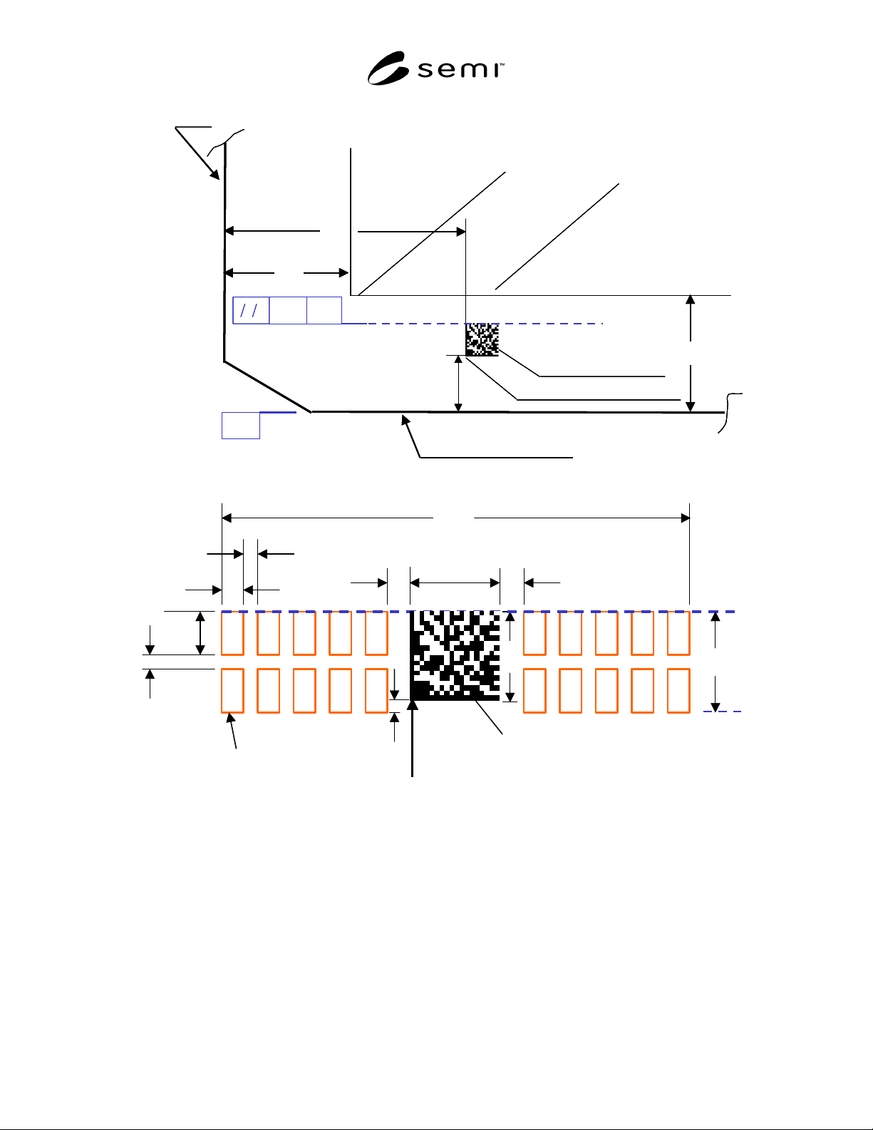
SEMI D32-0303 © SEMI 2003 4 A 24 3 01 7 9 56 8 B A Data Matrix Field Short Edge Long (Neare st) Edge Quality Area E E Orientation Corner Mark Re ference Point BC D E FGH I J T -S- -S- A 24 3 01 7 9 56 8 B A Data Matrix F…
SEMI D32-0303 © SEMI 2003 3
7.7.3.3 Consist of two sets of two-line strings as shown
in Figure 2.
7.7.4 The order of the alphanumeric characters shall be
as agreed upon between supplier and user.
NOTE 1: A typical sequence could be: The message begins
at the upper leftmost window, progresses horizontally to the
upper rightmost window, continues at the lower leftmost
window and ends at the lower rightmost window.
7.8 Quiet Zones
7.8.1 The space between the Data Matrix code symbol
and adjacent alphanumeric symbols shall be 0.48 mm.
7.8.2 A 0.50 mm wide quiet zone surrounds the entire
mark field.
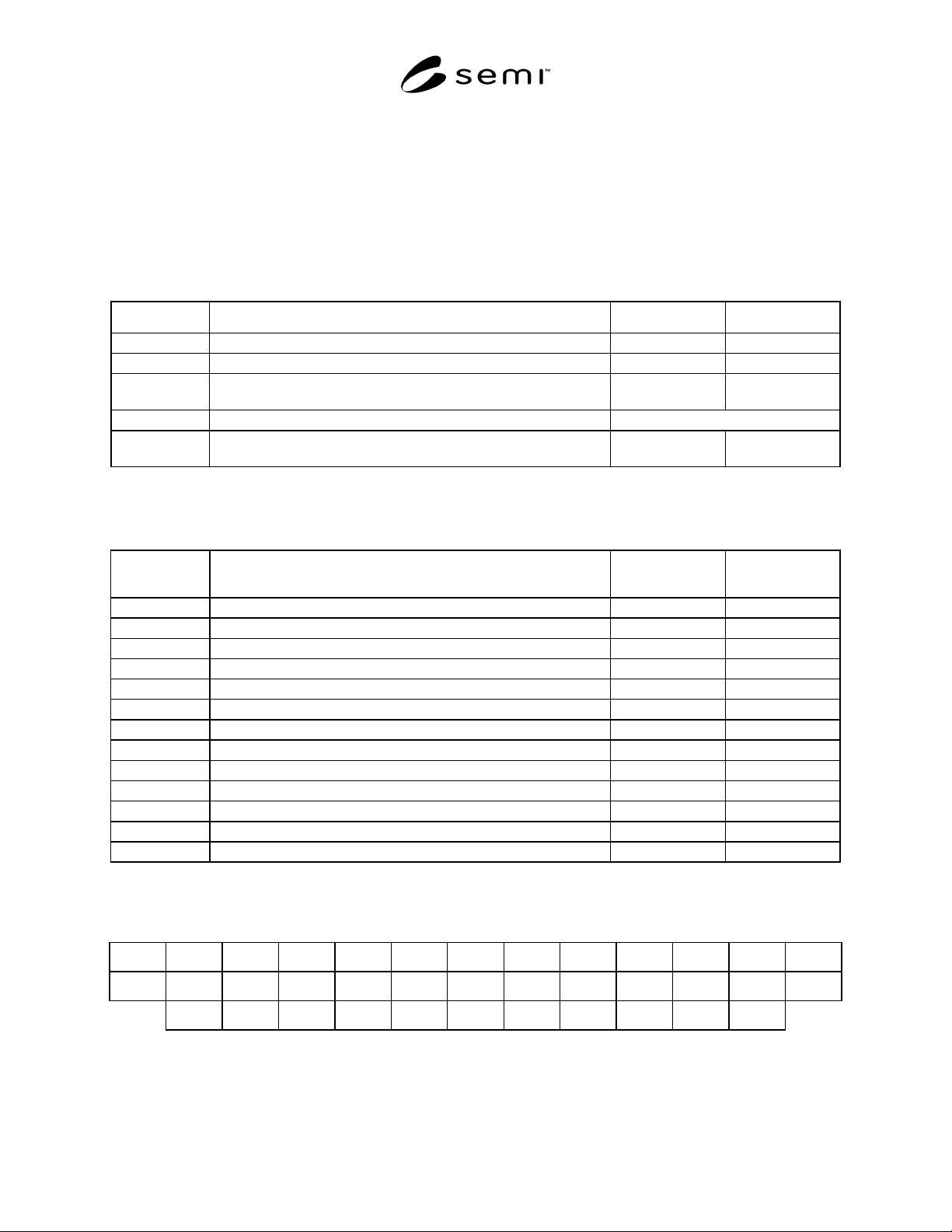
Table 1 Mark Location Dimensions (see Figure 1)
Letter Symbol Name of Dimension Nominal Value, mm Tolerance, mm
A Edge to Mark Reference Point 15.0 ± 0.5
B Nearest Edge to Mark Reference Point 2.5 ± 0.5
E Edge to Quality Area 5.0
Reference
(See Note 1.)
– S – Reference Line parallel with substrate edge Reference (See Note 2.)
T
Top of Mark Field to Reference Line Parallelism across Mark Area
Width (L) (see Table 2 and Figure 3)
≤1.0 TIR
NOTE 1: This is a reference dimension.
NOTE 2: This line is a virtual reference line.
Table 2 Mark Field Dimensions (see Figures 2 and 3)
Letter Symbol Name of Dimension Nominal Value, mm
Tolerance, mm
(See Note 1.)
C
2
Data Matrix Field Width 1.44
D Mark Field Width 8.32
F Mark Field Height 1.60
G Bottom of Mark to Mark Reference Point 0.20
H Alphanumeric Character Window Height 0.72
I Alphanumeric Character Window Width 0.40
J Alphanumeric Character Window Horizontal Separation 0.24
K Alphanumeric Character Window Vertical Separation 0.16
L Mark Area Width 9.32
M Mark Area Height 2.60
Q
1
Data Matrix Quiet Zone, Horizontal 0.48
Q
2
Mark Area Quiet Zone, Width and Height 0.50
R
2
Data Matrix Field Height 1.44
NOTE 1: The laser marker can control these field dimensions to much tighter tolerances than it can control the field location. For that reason it
is not necessary to apply tolerances to these values and it is appropriate to define these dimensions with two decimal places.
Table 3 Modified SEMI OCR Character Set
A B C D E F G H I J K L M
N O P Q R S T U V W X Y Z
1 2 3 4 5 6 7 8 9 0 –
SEMI D32-0303 © SEMI 2003 4
A
24301
7
9
56 8
B
A
Data Matrix Field
Short Edge
Long (Nearest) Edge
Quality Area
E
E
Orientation
Corner
Mark Reference Point
BCDE
FGH I J
T-S-
-S-
A
24301
7
9
56 8
B
A
Data Matrix Field
Short Edge
Long (Nearest) Edge
Quality Area
E
E
Orientation
Corner
Mark Reference Point
A
24301
7
9
56 8
B
A
Data Matrix Field
Short Edge
Long (Nearest) Edge
Quality Area
E
E
Orientation
Corner
Mark Reference Point
BCDE
FGH I J
T-S-
-S-
Figure 1
Data Matrix Field Location
H
K
A/N Character Window
I
Mark Reference Point
Data Matrix Field
G
J
R
2
C
2
Q
1
F
D
Q
1
H
K
A/N Character Window
I
Mark Reference Point
Data Matrix Field
G
J
R
2
C
2
Q
1
F
D
Q
1
Figure 2
Mark Field Dimensions
SEMI D32-0303 © SEMI 2003 5
D
L
M
Mark Reference
Point
F
Q
2
Q
2
Q
2
Q
2
D
L
M
Mark Reference
Point
F
Q
2
Q
2
Q
2
Q
2
D
L
M
Mark Reference
Point
F
Q
2
Q
2
Q
2
Q
2
D
L
M
Mark Reference
Point
F
Q
2
Q
2
Q
2
Q
2
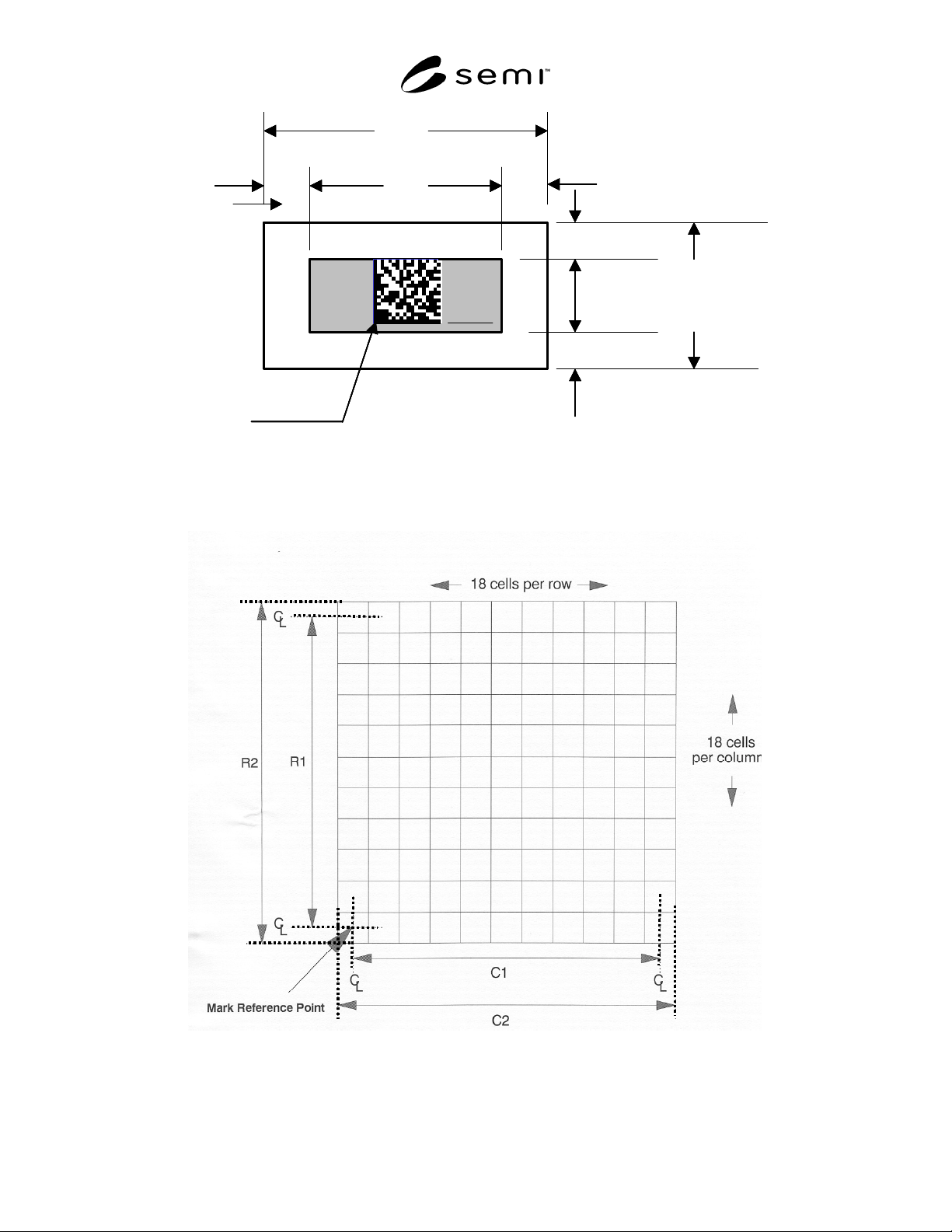
Figure 3
Mark Area Dimensions
Figure 4
Data Matrix Field