semi合集-English.pdf - 第1505页
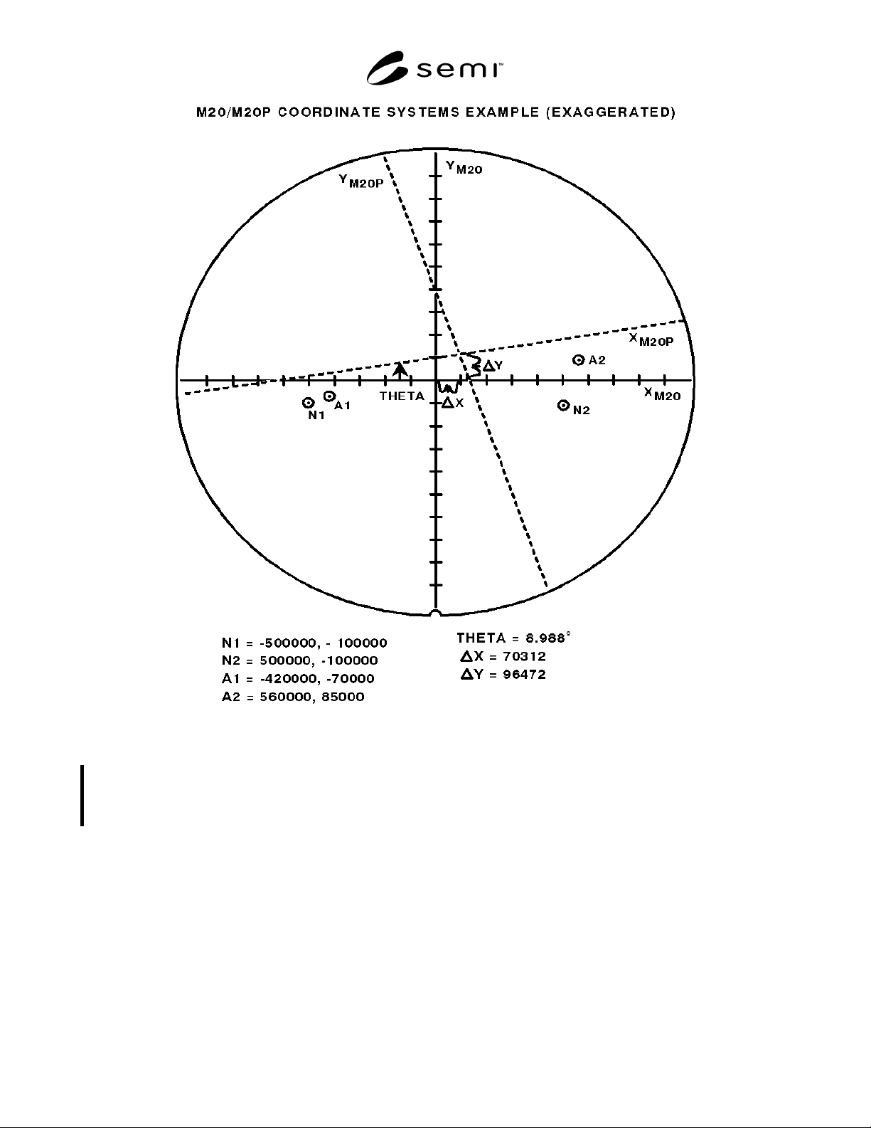
SEMI E30.5-0302 © SEMI 2001, 2002 33 Figure R1-1 M20/M20P Co ordinate System s Exam ple R1-5 Multi Measure ment Station Metro logy Equipment — MSEM im ple mentation on metrology equipment with multiple measure ment stati…

SEMI E30.5-0302 © SEMI 2001, 2002 32
Where C and D are the adjusted site 1 coordinates in a rotation-adjusted coordinate system calculated, for example,
using the formulas:
C = yA1 - ((xN1 sin Θ) + ((yN1 cos Θ)
D = xA1 - ((xN1 cos Θ) - ((yN1 sin Θ)
R1-4.7 The equipment can also calculate a SCALEFACTOR term to indicate the relative difference between the
length of the vector connecting the nominal alignment sites and the length of the vector connecting the actual
alignment sites. This can be used, for example, to judge whether there is a problem with the alignment process,
since the difference between these two vectors should be small.
SCALEFACTOR
VA
V
N
=
where VA and VN are the length of the vectors connecting the actual and nominal alignment sites, calculated using
the formulas:
()()
VN yN yN xN xN=−+−
21
2
21
2
()()
VA yA yA xA xA=−+−
21
2
21
2
SEMI E30.5-0302 © SEMI 2001, 200233
Figure R1-1
M20/M20P Coordinate Systems Example
R1-5 Multi Measurement Station Metrology Equipment — MSEM implementation on metrology equipment with
multiple measurement stations should follow guidelines setablished for multi-processing station SEMS such as the
Apply and Develop Track Specific Equipment Model (SEMATECH ID #: 95113021AENG Title: SEMATECH
Apply/Develop Track Specific Equipment Model (ADTSEM), Version 0.8, January 4, 1996).
NOTICE:. SEMI makes no warranties or representations as to the suitability of the standards set forth herein for
any particular application. The determination of the suitability of the standard is solely the responsibility of the user.
Users are cautioned to refer to manufacturer’s instructions, product labels, product data sheets, and other relevant
literature respecting any materials mentioned herein. These standards are subject to change without notice.
The user’s attention is called to the possibility that compliance with this standard may require use of copyrighted
material or of an invention covered by patent rights. By publication of this standard, SEMI takes no position
respecting the validity of any patent rights or copyrights asserted in connection with any item mentioned in this
standard. Users of this standard are expressly advised that determination of any such patent rights or copyrights, and
the risk of infringement of such rights, are entirely their own responsibility.
Copyright by SEMI® (Semiconductor Equipment and Materials
International), 3081 Zanker Road, San Jose, CA 95134. Reproduction o
f
the contents in whole or in part is forbidden without express written
consent of SEMI.

SEMI E32-0997 © SEMI 1994, 19971
SEMI E32-0997
MATERIAL MOVEMENT MANAGEMENT (MMM)
CONTENTS
1 Introduction
1.1 Purpose
1.2 Scope
1.3 References
1.4 Conventions
1.4.1 State Models
1.4.2 Object Services
2 Definitions
3 Overview
3.1 Macro and Micro Levels
3.2 Ports and Locations
3.3 Compliance
4 Macro Level
4.1 Macro Level Concepts
4.1.1 Macro Level Definitions
4.1.2 Atomic Transfer
4.1.3 Compound Transfer
4.1.4 Parallel Transfers
4.1.5 Transfer Recipe
4.1.6 Transfer System Controller as Transfer
Agent
4.1.7 Transfer Job
4.2 Macro Level Behavior
4.2.1 Macro Level Communications
4.2.2 Transfer Job State Model
4.2.3 Atomic Transfer State Model
4.3 Extended Behavior Models
4.3.1 Extended Communications
4.3.2 Extended Transfer Job State Model
4.3.3 Extended Atomic Transfer State Model
4.4 Macro Level Services
4.4.1 Service List
4.4.2 Service Detail
4.4.3 Parameter/Attribute Definitions
4.5 Object Attribute Definitions
4.5.1 Equipment
4.5.2 TransferJob Object
4.5.3 AtomicTransfer Object
5 Micro Level
5.1 Micro Level Concepts
5.1.1 Micro Level Definitions
5.1.2 Micro Level Description
5.2 Micro Level Behavior
5.2.1 Micro Level Communications
5.2.2 Micro Level Messaging via Host
5.3 Extended Behavior
5.4 Micro Level Services
5.4.1 Service List
5.4.2 Service Detail
5.4.3 Parameter Definitions
Application Notes
A1-1 Transfer-Related Mechanisms
A1-1.1 Example Port State Model
A1-1.2 Additional Related Mechanisms
A1-2 WIP Tracking
A1-3 Error Handling
A1-3.1 Macro Level Error Handling
A1-3.2 Micro Level Error Handling
A1-4 Practical Applications
A1-4.1 Passive Transfer
A1-4.2 Active Transfer/Exchange of Cassettes
A1-4.3 Sequential Moves
A1-4.4 Linked Lithography
A1-4.5 Non-Compliant Transfer Partner
Index
List of Tables
Table 4.1 Transfer Job State Transition Table