semi合集-English.pdf - 第7850页
SEMI T13-1104 © SEMI 2004 10 Ci r cui t M odu l e Die Mo ther S ubs tr a te D i c i ng F r am e Wa fe r Le ad F ram e PC B C abi n et 0 .. * G l ass P l a te Tr ay Ta p e St r ip Di e T r ac e Da ta (DT D) char acte r i …
SEMI T13-1104 © SEMI 2004 9
Substrate
Die
0..*
Batch Lot
0..*
OR
1..* 1..*
1..*
Figure 6
Lot vs. Batch
9.4.2 Die-trace Die Data (DDD) — This is Die Trace
Data for a die on a certain process. Examples of the
data are electric test classification information often
referred to as BIN code and wire bonding inspection
data for a die.
9.4.3 Die-trace Map Data (DMD) — Die-trace Die
Data are often grouped together on the process which is
executed on a mother substrate. The grouped data is
referred to as a map and is usually two-dimensional
array or matrix. Examples are probing test data and die
ID map of mounting/inserting data on PCB or lead
frame strip.
9.4.4 Die-trace Substrate Data (DSD) — This Die
Trace Data is specific for a substrate on a certain
process. Examples of the substrate are wafer, glass plate
for flat panel display, such strip as PCB and so on. This
data has no special distribution on the substrate or may
have some distribution but may not be a Die-trace Map
Data. Sometimes this data has very strong correlation
with most Die-trace Die Data on the substrate when, for
example, this data shows remarkable deviation from
normal process result. So the Die-trace Die Data need
to keep linkage with this data for complement.
9.4.5 Die-trace Lot Data (DLD) — This Die Trace
Data is specific for a lot on a certain process. Lot is a
group of material or products for the sake of expedient
to produce a specific product. A unit of a lot may be
different on each process or product. The lot here
doesn’t include group just for delivery. Because of
similar linkage as Die-trace Substrate Data, the data
need to keep linkage with this data for complement.
9.4.6 Die-trace Batch Data (DBD) — This Die Trace
Data is specific for a batch on a certain process. Batch
is a group of material or products for the sake of
expedient to execute a process. A unit of a batch may
be different on each process or equipment. Because of
similar linkage as Die-trace Substrate Data, the data
need to keep linkage with this data for complement.
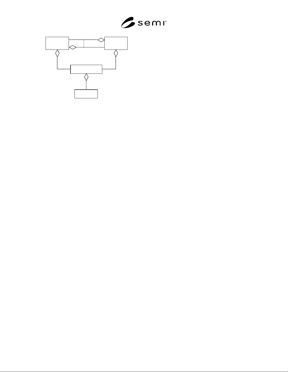
9.4.7 Lot versus Batch — Because lot and batch are
both a group of material or products, their unit sizes are
alternative. However sometimes the unit of a lot may be
smaller than that of a batch on a process, the relation
may be opposite on the other process for the same
product, as illustrated on Figure 6. Lot is more related
to production plan, production strategy or sprit/merge
operation. While, batch is close to process or equipment
type, configuration and structure.
9.5 Physical Substrate Model — Because die tracing
may need to be started from very early manufacturing
process and completed at the such final product as cell
phone and Television set, there are many different types
of substrates appears as objects of tracing: e.g. wafer,
die and PCB. While their appearances are fairly
different, some characteristics are common. It is
convenient to separate the common nature as a base
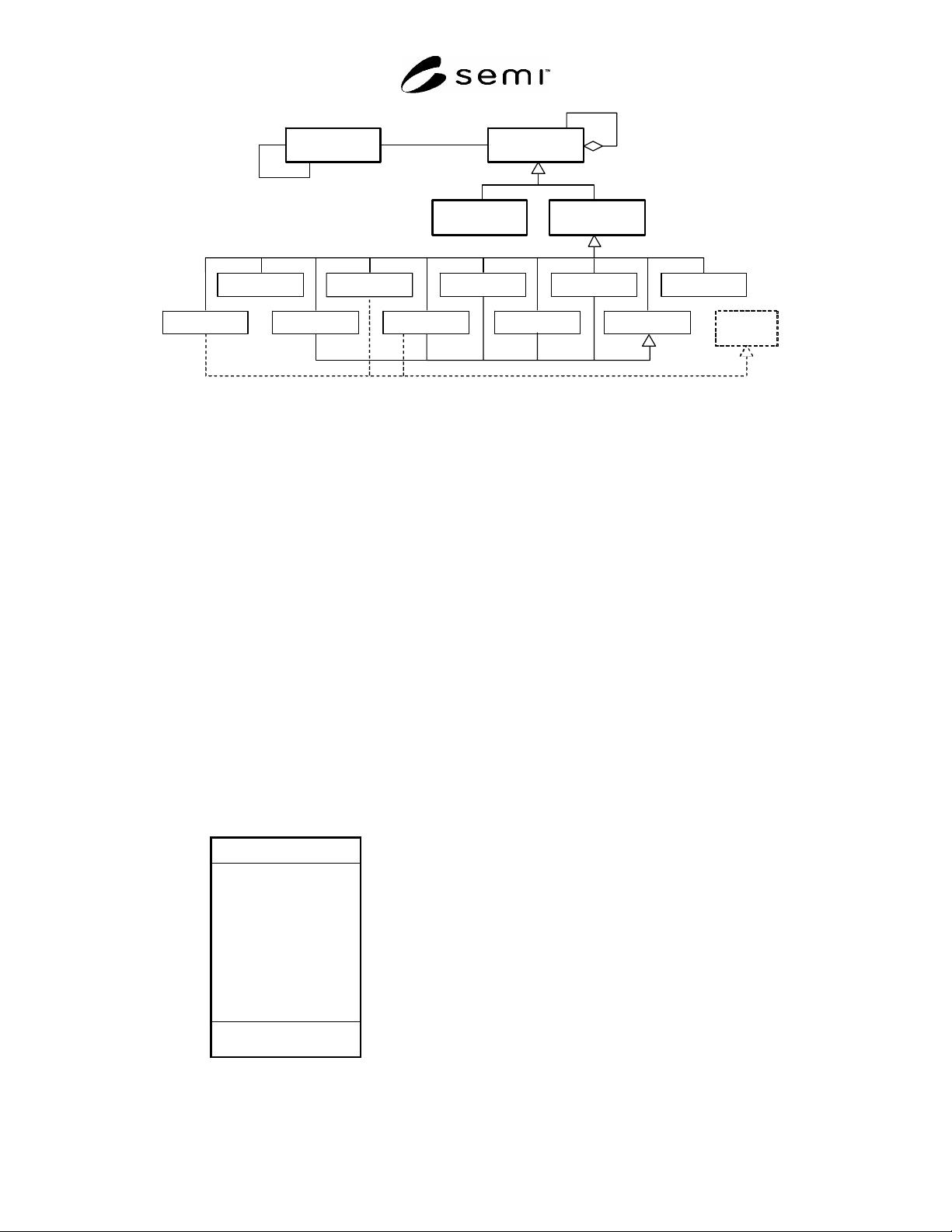
class object, as illustrated on Figure 7. Also the class
diagram shows which will be physical tracing target
and helps understanding which target make which Die
Trace Data. This diagram gives just taxonomy of die
trace target substrate in a sense.
9.5.1 Circuit Module — This class represents any
modular electric circuit and is the common part of any
substrate appears as an object of die tracing. Each
Circuit Module in die tracing world has corresponding
Die Trace Data. The Die Trace Data may link to the
other subtype of Die Trace Data: e.g. as aggregation or
complement. Circuit Module may have smaller grain
Circuit Modules on it as components. For example,
such a strip as PCB or linked lead frames has dice. This
class has subclasses: Die and Mother Substrate.
SEMI T13-1104 © SEMI 2004 10
Circuit Module
Die
Mother
Substrate
Dicing FrameWafer Lead Frame PCB Cabinet
0..*
Glass Plate Tray Ta pe Strip
Die Trace Data
(DTD)
characterizes
0
..*
refers
links
0
..*
Cassette
Reusable
Container
Figure 7
Physical Substrate Model for Die Tracing
9.5.1.1 Circuit Module Class Definition — Circuit
Module has such attribute as ID, Type and etc. as
depicted on Figure 8. These attributes cannot be
changed because they are proper for a specific Circuit
Module and not all attributes are illustrated on the
figure. Because this document doesn’t intend these
attributes to be accessed directly but just for reference
to specify services to access or make use of these
attributes. This class is used to discuss and handle
generic issues of any subclasses.
9.5.1.2 Responsibility of Circuit Module — Because
Circuit Module class is to be material label or material
property sheet, responsibility of this class is to play the
role.
9.5.1.3 Services of Circuit Module — To complete the
responsibility, this class provides the following
services.
9.5.1.3.1 showProperty — This service returns all or a
part of attributes of this object.
CircuitModule
showProperty
showDaughter
ID
Type
ProductName
Manufacturer
Plant
Location
ProductionStage
LatestProcessTime
Lot
… … ..
Figure 8
Circuit Module Class
9.5.1.3.2 showDaughter — This service is to get
smaller grain Circuit Modules which this Circuit
Module has on it.
9.5.1.4 Behavior of Circuit Module — Behavior is
defined to complete responsibility of the Circuit
Module. The behavior is often specified through
collaboration with outside of this class and state model.
Because this class has services to access internal
attributes, it defines no collaboration. Also this class
defines no state model for it is stateless.
9.5.2 Die — This class represents a semiconductor die
fabricated on wafer. It doesn’t matter how it appears: on
the way of fabrication on a wafer, diced and mounted
on some substrate or it is packaged. As long as it is
fabricated through semiconductor process or equivalent
process, it must be a die regardless of base material. Die
doesn’t aggregate the other Circuit Modules and it is
not aggregated by the other Die. In these senses, dice
for gallium arsenide devices, linear image sensors and
flat panel display (FPD) devices are examples of the
die.
9.5.2.1 Die Class Definition — Die inherits Circuit
Module. Class definition of the Die is almost same as
one for Circuit Module except it may not have a service
showDaughter. Even if the service is implemented, it
returns error or no daughter Circuit Modules.
9.5.3 Mother Substrate — This class is a Circuit
Module which may consist of one or more the other
Circuit Modules. Silicon wafers, lead flames, IC trays
and print circuit boards (PCBs) are examples of Mother
Substrate. Because it is a derived class of Circuit
Module to exclude the Die class, it must be the Mother
Substrate as long as it is used for the purpose, even if it

SEMI T13-1104 © SEMI 2004 11
has not mounted any other Circuit Modules yet or it is
on the way of fabrication.
9.5.3.1 Mother Substrate Class Definition — Mother
Substrate inherits Circuit Module. Class definition of
the Mother Substrate is completely same as one for
Circuit Module. This class is redefined to separate class
Die from the other Circuit Module classes for
convenience.
9.5.4 Wafer — This is a type of Mother Substrates
which represents thin disc shape semiconductor
material to fabricate semiconductor devices on it.
Examples are 300 mm diameter silicon wafers and 3
inches diameter gallium arsenide wafers. Some case a
few hundreds of microprocessor dice may be fabricated
on it.
9.5.5 Glass Plate — This is a type of Mother Substrats
which represents thin transparent rectangular glass plate
to fabricate flat panel display devices on it. However it
is usually rectangle, sometimes it may be such other
shape as circle. Some case length of one of ridge is
beyond one meter.
9.5.6 Dicing Frame — This is a type of Mother
Substrates which represents thin rectangular flame
which centers a piece of elastic sticky film to keep a
wafer for dicing. Dicing frame is usually reusable.
9.5.7 Cassette — This is a type of Mother Substrates
which represents one of reusable container to store and
carry Circuit Modules. Contained Circuit Modules are
positioned. Examples are wafer carriers, wafer shipping
boxes, dicing frame magazines and IC trays.
9.5.8 Tray — This is a type of Mother Substrates
which represents a kind of cassettes which holds dice
on two dimensional surface of it. It is often used to
move dice to next process, ship or test.
9.5.9 Lead Frame — This is a type of Mother
Substrates which represents base of a die to package as
a semiconductor device. It has many electrodes to
connect with electrode pads of the die. A few Lead
Frames are often physically linked together before
packaging is completed for convenience of production.
In this sense Lead Frames are a kind of Strip described
later.
9.5.10 Tape — This is a type of Mother Substrates
which represents very long narrow strip flexible
substrate made of plastic film, cloth, paper or hybrid
material to hold electronics elements or small parts for
carrying, feeding or shipping. Usually it is rolled on a
magazine for handling.
9.5.11 PCB — Print Circuit Board. Hard or flexible
substrate with one or multiple layered circuit wiring
conductor patterns an active/passive electronics
elements on one of or both surfaces. This is also a type
of Mother Substrates.
9.5.12 Strip — Usually rectangular or tape shaped
substrate to mount electronics parts. This is also a type
of Mother Substrates.
9.5.13 Cabinet — An enclosure for electronics to keep
from exposure of electrode and/or subcomponents,
and/or to give some means of human operation. Often it
contains PCBs and power supply module with switches
and such display devices as light emission diodes and
flat display panel on it. This is also a type of Mother
Substrates.
10 Detail Concepts
10.1 System Wide Concept — Previous section
describes basic concepts of Die Tracing. Based on
these, this section describes more detailed concepts to
trace dice practically.
10.2
Die Trace System — A system for die tracing
ranges over any entity related to Die Trace Data of the
target Die. From the system point view, there must be
some managing objects to coordinate ensembles in the
system to achieve expected responsibility.
10.3 Die Trace System Linkage — Also it is difficult to
manage a lot of objects and data by just one manager. It
is expected to have more than one manager to
coordinate and manage data and such objects as
Machines and Tracers. They link together to organize a
kind of network as illustrated in the following figure.