semi合集-English.pdf - 第4780页
SEMI C54-1103 © SEMI 2003 10 11.4.4 Operating Procedures 11.4.4.1 Flow settings should not be ch anged once established. 11.4.4.2 Introduce the zero gas and a djust the instrument per manufacturer’s recom mendations to r…

SEMI C54-1103 © SEMI 2003 9
11.1.5.2 Inject the sample to be tested in same manner
as the calibration standard. Record the retention times
and peak area.
11.1.5.3 Repeat Section 11.1.5.2.
11.1.5.4 Compare the average peak areas of the
calibration standard to that of the sample being tested.
Calculate the concentrations of impurities as shown in
SEMI C3. The result may not exceed the specification
in Section 7 of this standard (see Note 12).
NOTE 12: Oxygen trap conditioned per manufacturer’s
recommendations using hydrogen, carbon monoxide, or blend
in helium.
11.2 Carbon Dioxide — This procedure is for the
determination of carbon dioxide in oxygen using a gas
chromatograph with a flame ionization detector and a
methanizer.
11.2.1 Detection Limit — 0.02 ppm
11.2.2 Instrument Parameters
11.2.3 Column(s): 2.3 m (91 in) by 1/8 in HayeSep Db
11.2.3.1 Carrier Flow: 50 cc/min nitrogen
11.2.3.2 Sample Volume: 5 mL
11.2.3.3 Temperatures:
Detector 275°C
Column 50°C
Methanizer 295°C
11.2.4 Calibration Standards — 0.1–1 ppm carbon
dioxide in oxygen.
11.2.5 Operating Procedures (See Note 13.)
NOTE 13: Sample and calibration sample are injected on
column to vent until oxygen, carbon monoxide, and methane
have eluted. Valve is returned to allow carbon dioxide to elute
onto methanizer and flame ionization detector.
11.2.5.1 Inject the calibration standard into the column
using a gas sampling valve. Record the retention times
and peak area. Order of elution is: Oxygen + carbon
monoxide, methane, carbon dioxide.
11.2.5.2 Inject the sample to be tested in same manner
as the calibration standard. Record the retention times
and peak area.
11.2.5.3 Repeat Section 11.1.10.2.
11.2.5.4 Compare the average peak areas of the
calibration standard to that of the sample being tested.
Calculate the concentrations of impurities as shown in
SEMI C3. The result may not exceed the specification
in Section 7 of this standard (see Note 17).
11.3 Carbon Monoxide and Hydrogen — This
procedure is for the determination of carbon monoxide
and hydrogen in oxygen using a gas chromatograph
with a reduction gas detector.
11.3.1 Detection Limit — 0.002 ppm
11.3.2 Instrument Parameters
11.3.2.1 Column(s): 2 m (80 in) by 1/8 in Molecular
Sieve 13×
11.3.2.2 Carrier Flow: 20 cc/min air
11.3.2.3 Sample Volume: 1 mL
11.3.2.4 Temperatures:
Detector 265°C
Column 105°C
11.3.3 Calibration Standards — 0.5 – 1 ppm hydrogen
and carbon monoxide in nitrogen or oxygen.
11.3.4 Operating Procedures
11.3.4.1 Inject the calibration standard into the column
using a gas sampling valve. Record the retention times
and peak area. Order of elution is: Hydrogen, carbon
monoxide.
11.3.4.2 Inject the sample to be tested in same manner
as the calibration standard. Record the retention times
and peak area.
11.3.4.3 Repeat Section 11.2.4.2.
11.3.4.4 Compare the average peak areas of the
calibration standard to that of the sample being tested.
Calculate the concentrations of impurities as shown in
SEMI C3. The result may not exceed the specification
in Section 7 of this standard.
11.4 Total Hydrocarbons — This procedure is for the
determination of total hydrocarbons in oxygen with a
total hydrocarbon analyzer.
11.4.1 Detection Limit — 0.05 ppm
11.4.2 Instrument Parameters
11.4.2.1 Flow Requirements:
11.4.2.1.1 Carrier Flow Rate: per manufacturer’s
recommendations
11.4.2.1.2 Purity: less than 0.05 ppm total
hydrocarbons
11.4.2.1.3 Sample Flow Rate: manufacturer’s
recommendations
11.4.3 Calibration Standards — 0.1–1 ppm methane in
oxygen.

SEMI C54-1103 © SEMI 2003 10
11.4.4 Operating Procedures
11.4.4.1 Flow settings should not be changed once
established.
11.4.4.2 Introduce the zero gas and adjust the
instrument per manufacturer’s recommendations to read
the quantity known to be in the zero gas.
11.4.4.3 Introduce the span gas standard and adjust the
instrument per manufacturer’s recommendations to read
the quantity known to be in the span gas. This result
may not exceed specification in Section 7 of this
standard.
11.5 Water — This procedure is for the determination
of trace moisture (water) in O
2
using a continuous
flowing piezoelectric hygrometer (see Note 5, 6, 7 in
Section 9.4).
11.5.1 Detection Limit — 5 ppb
11.5.2 Flow Requirements — Set the sample pressure
and flow rate in accordance with the instrument
manufacturer’s instructions.
11.5.3 Calibration Standards — Construct a
calibration curve that contains at least three points
covering the range of interest. Verify the standards
employed independently by another analytical method.
11.5.4 Operating Procedure
11.5.4.1 Obtain a continuous flow sample of gas from
the source using a clean and passivated stainless steel
line that has been purged dry after exposure to ambient
moisture.
11.5.4.2 After prepurging with a dry gas, allow the
sample gas to flow through the sampling system and the
piezoelectric moisture hygrometer until a stable reading
is obtained.
11.5.4.3 Determine the moisture content of the oxygen
sample by comparing the reading to calibration curve.
The result may not exceed the specification in Section 7
of this standard.
SEMI C54-1103 © SEMI 2003 11
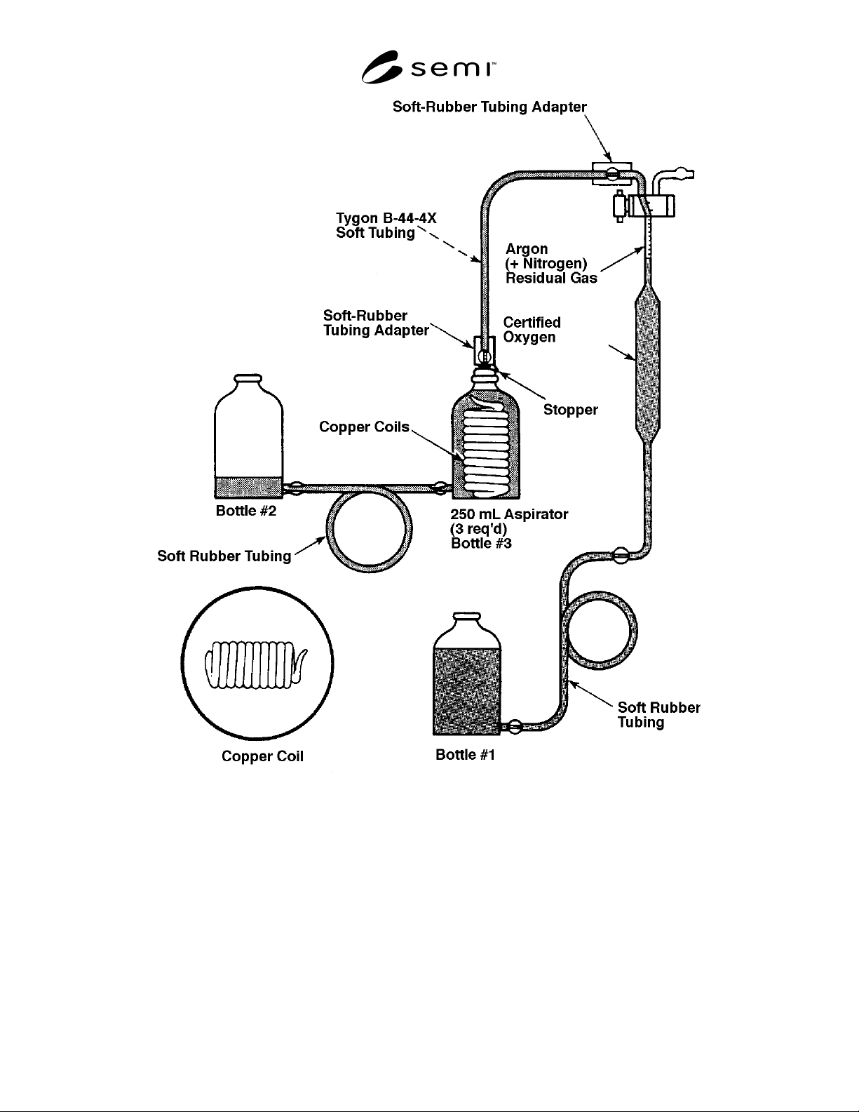
Buret
Figure 1
“Orsat” Device for the Assay Of O
2