semi合集-English.pdf - 第616页
SEMI E84-0305 © SEMI 1999, 2005 14 Phy sical Ha ndoff Handshake Active Handshake En gaged Handoff Request Handoff A ctive TP1, T A2 Tim eout TP2 Time out TA3, T P5 Tim eout for continuous handoff TA1 T imeout TA1, T P6 T…
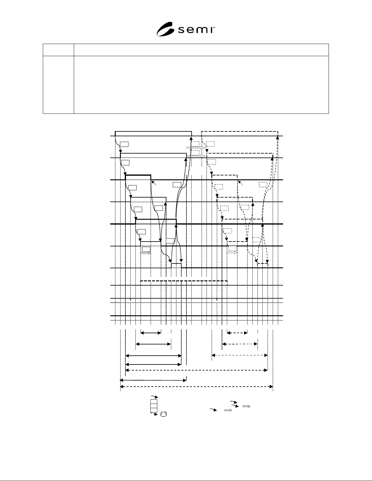
SEMI E84-0305 © SEMI 1999, 2005 13
Zone Definition/Description
Physical
Handoff
F to H
This zone is inclued in “Handoff Active”. This zone indicates that the active equipment is engaged in physically
delivering or removing FOUP to/from the equipment.
One carrier is loaded or unloaded if CS_0 or CS_1 is ON.
Two carriers are loaded or unloaded if CS_0 or CS_1 are ON
Start at: BUSY ON
End at: BUDY OFF
Requirements – Active equipment is required to start the movement to load/unload carrier and completely move
out from handoff conflict area.
CS_0
(CS_0 ON to specify left load port, CS_1 ON to specify right load port,
CS_1
CS_0 and CS_1 ON to specify simultaneous handoff)
(A to P)
VALID
(A to P)
L_REQ
(L_REQ ON to assign load port for LOAD
U_REQ
U_REQ ON to assign load port for UNLOAD)
(P to A)
carrier is carrier is
detected detected
TR_REQ
(A to P)
READY
(P to A)
BUSY
(A to P)
COMPT
(A to P)
CONT
(CONT ON to assign continuous handoff)
(A to P)
HO_AVBL
(P to A)
ES
(P to A)
<boundary>
A B C D E F
G H I J K L M N A B C D E F G H I J K L M N
<zone>
Physical Handoff Physical Handoff
Handoff Active
Handoff Active
Handoff Request Handoff Request
Handshake Engaged (non-continuous)
Handshake Engaged (non-continuous)
Handshake Active (non-continuous)
Handshake Active (continuous)
Relation of signals
Active Equipment Timer related to
Passive Equipment Timer related to or
Delay Timer related to or
for continuous handoff use only
TD1
TP6 TD0
TP1
TP2
TP3
TP4
TP5
TA1
TA2
TA3
TD0
TP1
TP2
TP3
TP4
TP5
TA1
TA2
TA3
TDx
TAx
TPx
Figure 10
Summary of Time Diagram
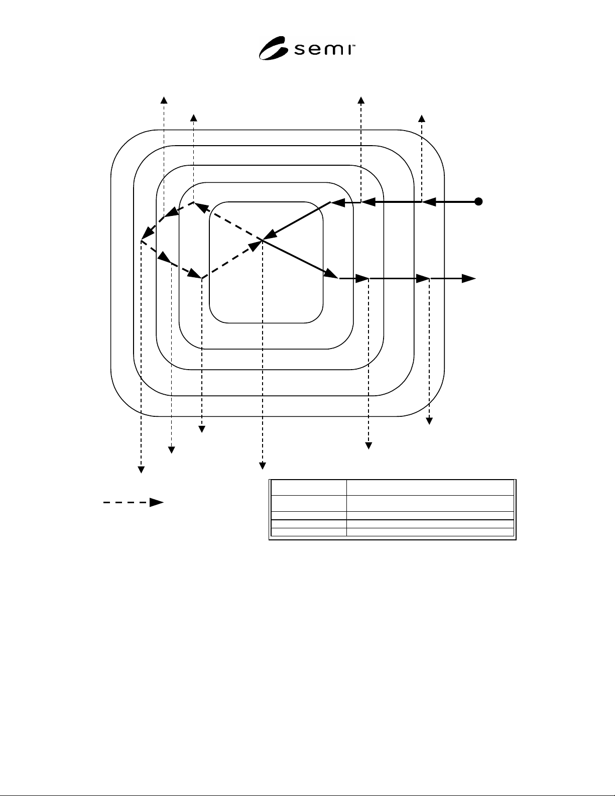
SEMI E84-0305 © SEMI 1999, 2005 14
Physical Handoff
Handshake Active
Handshake Engaged
Handoff Request
Handoff Active
TP1, TA2 Timeout
TP2 Timeout
TA3, TP5 Timeout
for continuous handoff
TA1 Timeout
TA1, TP6 Timeout
TP3, TA4, TP4 Timeout
TP2 Timeout
TA3, Timeout
TP1, TA2 Timeout
TP5 Timeout
Handshake Active Start: VALID ON / End: VALID OFF (last VALID OFF
for continuous handoff)
Handshake Engaged Start: L_REQ ON or U_REQ ON / End: COMPT OFF
(last COMPT OFF for continuous handoff)
Handoff Request Start: L_REQ ON or U_REQ ON / End: COMPT OFF
Handoff Active Start: READY ON / End: COMPT ON
Physical Handoff Start: BUSY ON / End: BUSY OFF
Figure 11
State Transition Model
6.2.4 Single Handoff Sequence (loading/unloading)
6.2.4.1 The time diagrams of the loading and unload-ing operations in single handoff are shown in Figures 12 and
13, respectively. The sequence shown in Figures 12 and 13 is:
1)
After the active equipment (AMHS equipment) reaches the handoff location in front of the load port, the active
equipment specifies the load port number at which the active equipment is to handoff a carrier to the passive
equipment using CS_0 and CS_1.
2) The active equipment turns the VALID signal ON. It shows that the signal transition of CS_0 and CS_1 is
valid.
NOTE 2: The passive equipment should not verify if the CS_0 or CS_1 signals are ON until after the active equipment has
turned the VALID signal ON, which signifies the interface communication is valid.

SEMI E84-0305 © SEMI 1999, 2005 15
3) The passive equipment turns the L_REQ signal ON if the load port is ready to perform loading operation and
turns the U_REQ signal ON if the load port is ready to perform unloading operation.
4) To request the passive equipment to start the carrier handoff operation, the active equipment turns the TR_REQ
signal ON.
5)
The passive equipment turns the READY signal ON when the passive equipment is ready for the handoff of the
carrier.
6)
After confirming the READY signal is ON, the active equipment turns the BUSY signal ON and starts the
handoff operation.
7)
The passive equipment turns the L_REQ (U_REQ) signal OFF when a carrier is placed correctly on the load
port (when the carrier on the load port is removed).
8)
After the completion of the load or unload operation and after the active equipment is clear of the handoff
conflict area, the active equipment turns the BUSY signal OFF. The active equipment must confirm L_REQ
signal (U_REQ signal) is turned OFF before the BUSY signal turn OFF.
9) The active equipment turns the TR_REQ signal OFF after the BUSY OFF.
10) The active equipment turns the COMPT signal ON to inform the passive equipment about the completion of the
handoff operation.
NOTE 3: If the passive equipment verifies the BUSY and TR_REQ signals are OFF, it should verify these signals only after the
active equipment has turned the COMPT signal ON, which signifies the active equipment has completed the handoff operation.
11) After confirming that the active equipment turned the COMPT signal ON, the passive equipment turns the
READY signal OFF.
12)
After the READY signal is turned OFF, the active equipment turns the COMPT, VALID, CS_0, and CS_1
signals OFF.
13)
The handshake with the passive equipment is closed when the VALID signal is turned OFF.
NOTE 4: If the passive equipment checks for COMPT, VALID and CS_0 or CS_1 signals, it should allow the signals to turn
OFF in any order without reporting an error.
6.2.4.2 This section defines the Single Handoff Sequence between the OHS (interbay passive type vehicle) and
Stocker. The time diagrams of the loading and unloading operations in single handoff are shown in Figures 14 and
15, respectively. The sequence shown in Figures 14 and 15 is:
1) When the passive equipment (i.e., OHS) arrives at the active equipment (i.e., STOCKER), the passive
equipment specifies to the active equipment where the handoff will take place using VS_0 and VS_1.
2) At the same time as VS_set, the passive equipment turns the L_REQ signal ON if the load port is ready to
perform a loading operation or turns the U_REQ signal ON if the load port is ready to perform an unloading
operation.
3)
The passive equipment turns the VA signal ON. It shows that the signal transition of VS_0 and VS_1, L_REQ
or U_REQ is valid.
4)
After the active equipment recognizes the VA signal, it checks the VS_0 and VS_1, L_REQ and U_REQ signal
and turns the TR_REQ signal ON to request the passive equipment to start the carrier handoff operation.
5)
The passive equipment turns the READY signal ON when the passive equipment is ready for the handoff of the
carrier.
6) After confirming the READY signal is ON, the active equipment turns the BUSY signal ON and starts the
handoff operation.
7)
The passive equipment turns the L_REQ (U_REQ) signal OFF when a carrier is placed correctly on the load
port (When the carrier on the load port is removed).