semi合集-English.pdf - 第5938页
SEMI P40-1103 © SEMI 2003 4 Table 1 Flatness of the Mounting Surface Any Square Region with Specified Edge Length ( millim eters) Peak-to-Valley Flatness (nanometers) 150 48 75 24 40 12 25 8 20 6 10 3 Table 2 Clamping Pr…
SEMI P40-1103 © SEMI 2003 3
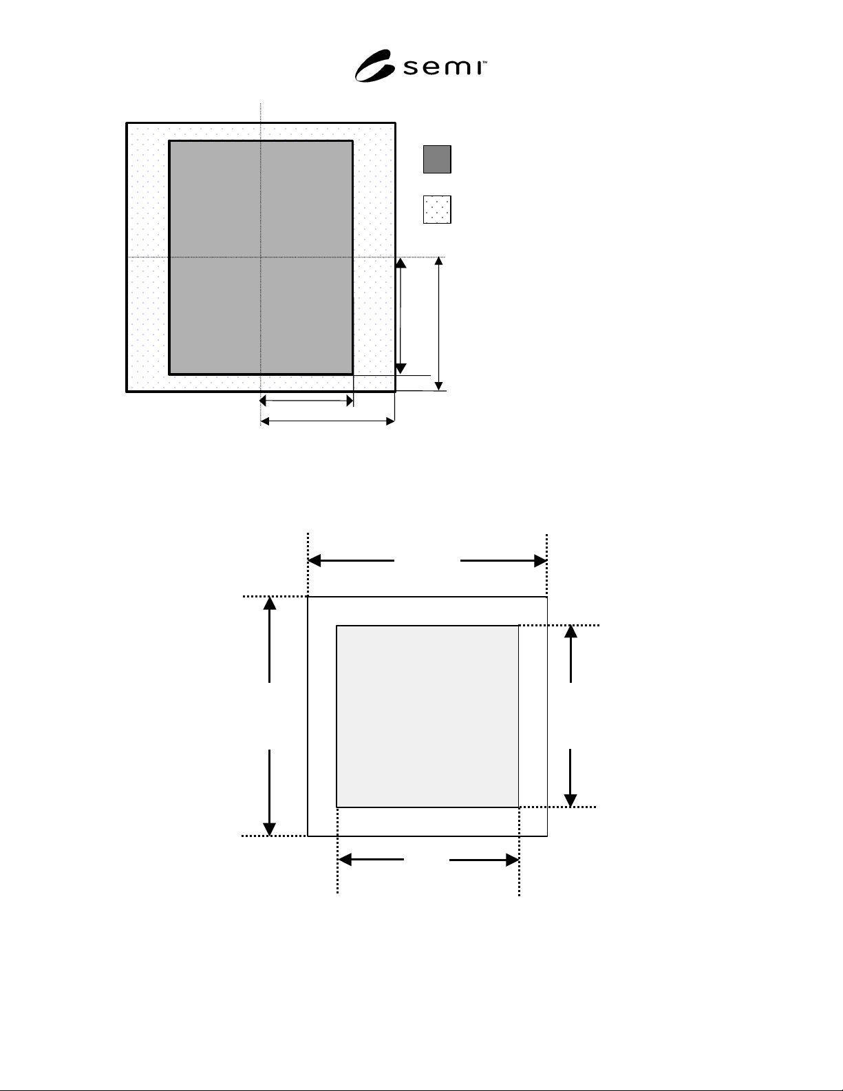
Maximum printable
field
(4x) 104 by 132 mm
(26 by 33 mm at
wafer)
A
rea reserved for
alignment marks, ID
marks, and handling
(The position of these
items are to be
negotiated between user
and supplier.)
A
rea for patterns printed on wafe
r
66.0
76.0
76.0
52.0
CL
CL
Figure 1
Layout of the Front Surface of the EUVL Mask, Showing Areas Reserved for Printed Patterns, ID Marks,
Alignment Marks and Handling
Units are in millimeters, and CL identifies the dotted lines as centerlines.
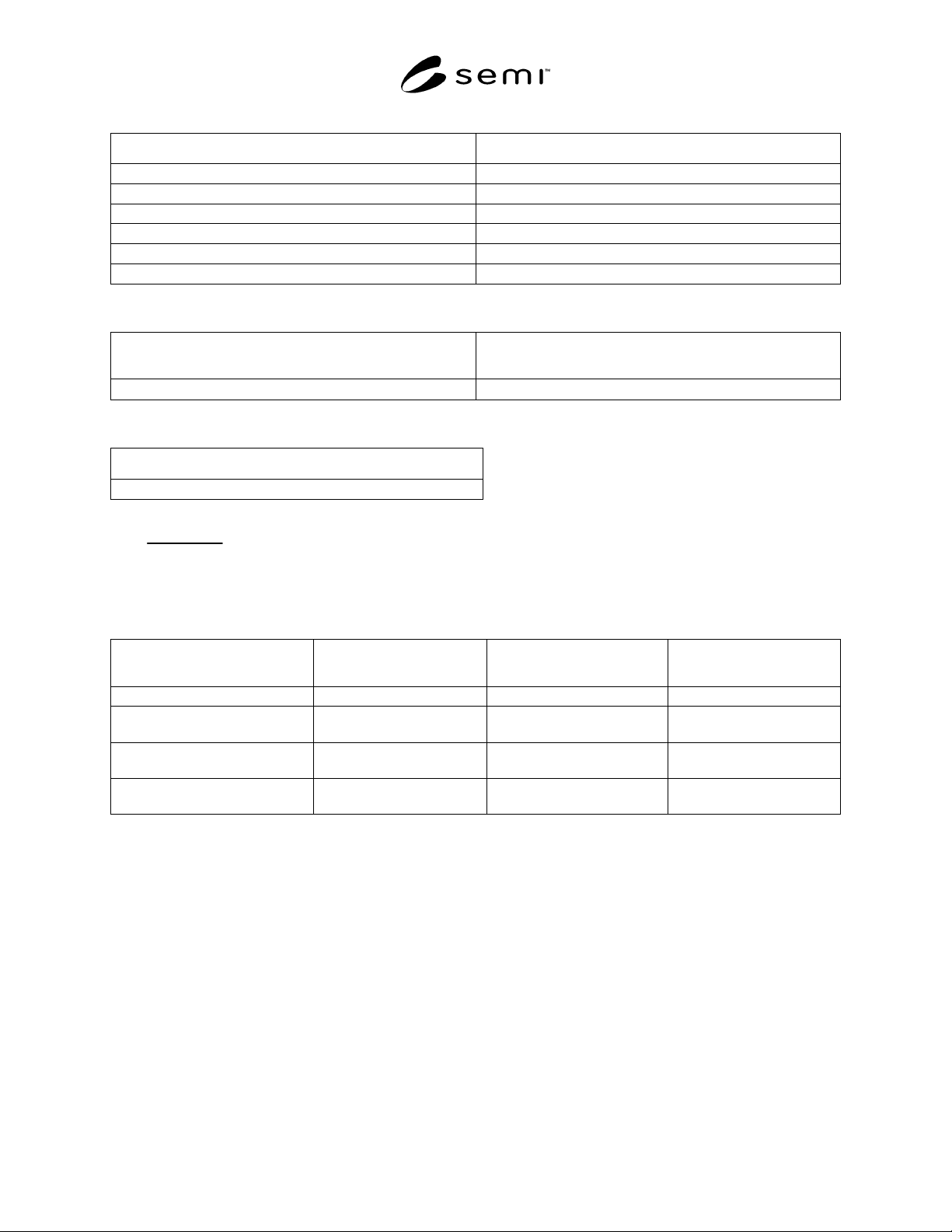
L
D
W
Mounting
quality
area
L
Figure 2
Dimensions of Mounting Quality Area
SEMI P40-1103 © SEMI 2003 4
Table 1 Flatness of the Mounting Surface
Any Square Region with Specified Edge Length (millimeters) Peak-to-Valley Flatness (nanometers)
150 48
75 24
40 12
25 8
20 6
10 3
Table 2 Clamping Pressure
Mean Clamping Pressure (KPa) Maximum Range of Clamping Pressure within Flatness Quality
Area (KPa)
15 ± 1.5
3.0
Table 3 Minimum Effective Bending Stiffness of the Chuck Cross Section
Bending Stiffness (Newton-meter) (See Note 1.)
30,000
NOTE 1: The effective bending stiffness (D) of a chuck with a solid cross section is given by:
D =
Eh
3
12 1 −
ν
2
()
where E is the elastic modulus in N/m
3
, h is the thickness in meters and ν is Poisson’s ratio.
Table 4 Dimensions of Pins or Pedestals on Chuck Surface
Parameter Label for parameter in
Figure 5
Units Required Value
Maximum spacing S
p
millimeters 10
Period P
p
millimeters To be agreed upon between
user and supplier
Angle of sidewall
θ
degrees To be agreed upon between
user and supplier
Pin height H
p
microns To be agreed upon between
user and supplier
SEMI P40-1103 © SEMI 2003 5
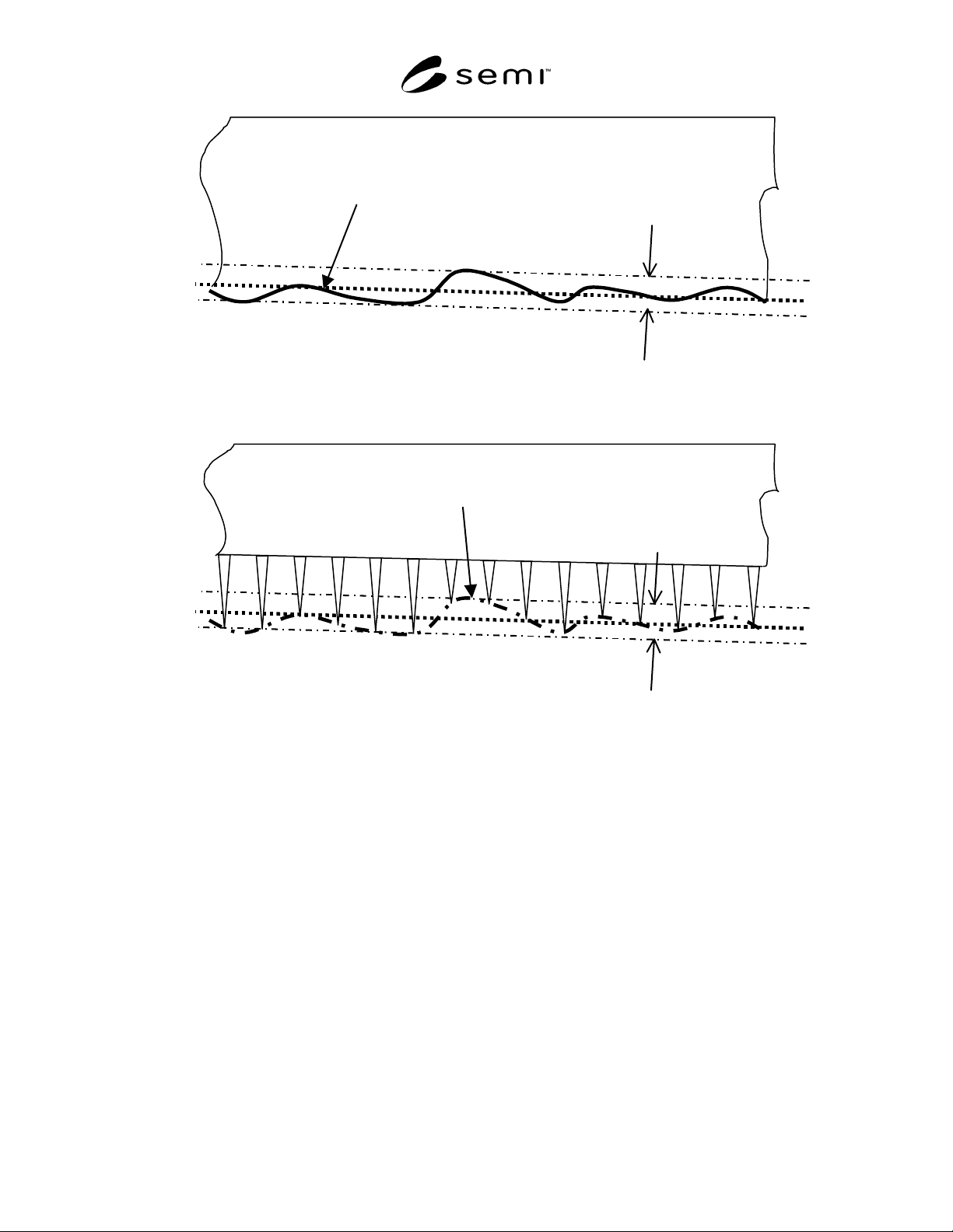
P
1
Mounting surface
Flatness error
Chuck
Figure 3
Definition of Flatness Error
P
1
is the best fit plane that minimizes the maximum deviation of the surface from P
1
.
P
1
Mounting surface
Flatness error
Chuck
Figure 4
Definition of Flatness Error for a Pin or Pedestal Chuck
P
1
is the best fit plane that minimizes the maximum deviation from the surface that passes through the
highest points on the chuck surface.