semi合集-English.pdf - 第3914页
SEMI F32-0998 © SEMI 1998 3 7.2 T est Secti on Requirements 7.2.1 Fix t uring of the test valve shal l b e made in accordance with ANSI/IS A-S75.02, Table 1, where the test valve is the complete valve assembly including …
SEMI F32-0998 © SEMI 1998 2
5.1.17 x — Ratio of pressure drop to absolute inlet
pressure, dimensionless, where:
x =
∆P
kPa
P
1
kPa
x =
∆P
psid
P
1
psia
ℜ
ℜ
ℜ
ℜ
ℜ
ℜ
5.1.18 x
T
— Ratio of pressure drop to absolute inlet
pressure (
∆
p/p
1
) at choked flow condition,
dimensionless.
5.1.19 Y — Expansion factor for compressible fluids,
where:
Y =1 −
x
3 × F
k
× x
T
5.2 Definitions
5.2.1 flow coefficient C
v
— A numer ic constant used
to characterize the flow capacity of a valve.
5.2.2 vapor pressure condensation point — Pressure
at which fluid phase changes from liquid to gas, for a
given upstream condition.
5.2.3 vena contracta — Point in a duct where the
diameter of the fluid stream is smaller than the diameter
of the duct.
6 Test Fluids
6.1 Incompressible (Liquid) Fluid — Water is the
standard liquid test fluid.
6.2 Compressible (Gaseous) Fluid — Nitrogen is the
standard gaseous test fluid. When using Nitrogen, care
should be taken to assure that the fluid does not
approach the vapor pressure condensation point at the
vena contracta.
7 Test Setup
7.1 Test Valve
7.1.1 The test valve can be any high purity valve, or a
combination of valve with tube connections, fittings
connection, or expanders which are normally attached
as part of the valve assembly as purchased. It is
important to note that the definition of the “test valve”
is inclusive of all connections and fittings, as supplied
by the manufacturer. This specifically differs from the
ISA procedure, whereby a method is provided to
differentiate the pressure drop contribution of the
attached fittings. It is recognized that flow coefficients
may vary slightly depending upon the end connection
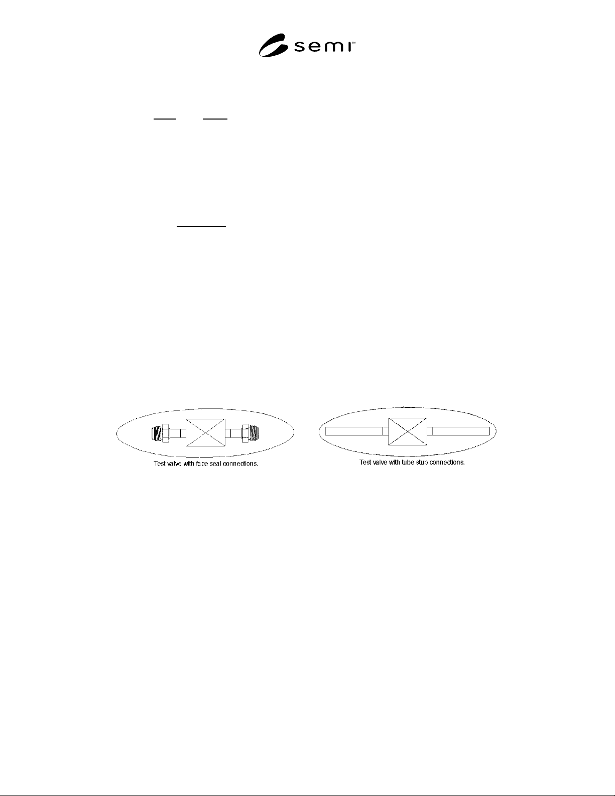
used. Examples of typical test valves are shown in
Figure 1.
Figure 1
Test Valve with Various Connections
SEMI F32-0998 © SEMI 19983
7.2 Test Section Requirements
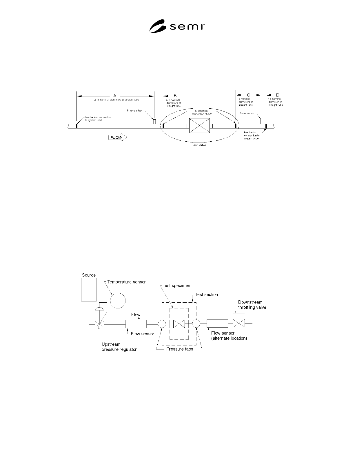
7.2.1 Fixturing of the test valve shall be made in accordance with ANSI/ISA-S75.02, Table 1, where the test valve
is the complete valve assembly including connections, as described above. For reference, ANSI/ISA-S75.02 test
setup is shown in Figure 2.
Figure 2
Fixturing Requirements, Standard Test Section
7.2.2 Tube Connections — Connect ions to the test valve are to be the same as would normally be performed by the
end user as installed. Tube connections are to be full penetration welded by automatic orbital head, with purge gas.
7.2.3 Face Seal Connections — Face seal connectors supplied with the test valve may be either male or female. An
appropriate mating connector shall be welded into the inlet and outlet tubing using full penetration orbital head
welds, and connected to the valve with standard seals.
7.2.4 Compression Fitting Connections — Valves supplied with tube stubs may be connected with compression
fittings.
8 Test Procedure
8.1 Setup — The test setup shall b e as shown in ANSI/ISA-S75.02, Section 3.1. For reference, see Figure 3. The
flowmeter may be upstream or downstream of the test valve, and can also be placed downstream of the throttle valve
when necessary to vent to atmosphere.
Figure 3
Test Setup

SEMI F32-0998 © SEMI 1998 4
8.1.1 Pressure Taps — Pressure tap s should be welded
into the system per ANSI/ISA-S75.02.
8.1.2 Pressure Measurement — Pressure measurement
devices can be analog gauge, electronic transducer, or
both. They should be calibrated to maintain the
minimum accuracy necessary for the governing flow
equations.
8.1.3 Throttle Valve(s) — A throttle valve shall be
positioned downstream. There is no valve style
restriction, however they should be sized sufficiently
for the required flowrate.
8.1.4 Flow Measurement — Depending upon the test
media, several types of flow measurement devices may
be used. These devices may include: turbine meter,
orifice plate, bell prover, mass flow meter, and timed
volumetric capture. Flow measurement devices should
be calibrated to maintain the minimum accuracy
necessary for the governing flow equations. All flow
measurements should be normalized to standard
conditions per ANSI 2530. Install and calibrate per
manufacturer’s recommended procedure.
8.1.5 Temperature Measurement — Temperature
measurement devices should be calibrated to maintain
the minimum accuracy necessary for the governing
flow equations.
8.2 Incompressible Fluid
8.2.1 Procedure
8.2.1.1 The test procedure is specified in ANSI/ISA-
S75.02, Section 5.1.
8.2.2 Test Limitations
8.2.2.1 It is critical that the absolute upstream pressure
meets the criteria specified in ANSI/ISA-S75.02,
paragraph 5.1.3, as referenced below:
P
1
kPa
=
2 ×∆P
kPa
F
L
2
P
1psia
=
2 ×∆P
psid
F
L
2
ℜ
ℜ
ℜ
ℜ
ℜ
ℜ
Equation 1
Absolute Upstream Pressure
8.2.2.2 The liquid pressure recovery factor, F
L
is
calculated from the maximum attainable flowrate, Q
max
.
If Q
max
cannot be experimentally determined, the value
of F
L
can be estimated. See the referenced section for
details.
8.3 Compressible Fluid
8.3.1 Procedure
8.3.1.1 The test procedure is specified in ANSI/ISA-
S75.02, paragraph 7.1.
8.3.2 Test Limitations
8.3.2.1 If possible, at least 3 data points should be
taken at flowrates where the fluid approaches
incompressible behavior. To attain these conditions, the
pressure drop ratio, x, should be less than or equal to
0.02. Additional data points should be taken at
increasing flowrates up to the maximum possible for
the system.
9 Coefficients Calculation
9.1 Flow Coefficient, C
v
9.1.1 The flow coefficient, C
v
, can b e calculated using
both incompressible and compressible fluids. For
incompressible fluids, ISA provides a relatively simple
method for determining C
v
. For compressible fluids, the
ISA test method for calculating C
v
requires the
determination of the choked flow pressure drop ratio,
x
T
,, and ultimately the expansion factor, Y, which
characterizes the valve geometry and fluid properties at
sonic velocities in the vena contracta. It has been
determined through considerable testing that the
expansion factor is critical in calculating actual pressure
drops across a valve when flow rates cause the fluid
density to change due to pressure and velocity changes.
9.2 Pressure Drop Ratio Factor, x
T
9.2.1 The ISA test method requires t he experimental
determination of the flow coefficient C
v
and a second
coefficient x
T
, the pressure drop ratio factor.
9.2.2 x
T
is equal to the critical pressu re ratio of the ISA
flow equation, and is close but not necessarily identical
to the experimentally observed pressure ratio at choked
flow. x
T
is chosen to correlate the experimentally
observed choked flow. The ISA equation will then
predict choking at a pressure drop ratio close to, but not
identical with, the experimentally observed value.
9.2.3 There are two methods to determine the pressure
drop ratio factor. The procedure of ANSI/ISA-S75.02,
Section 7.2 requires that C
v
be determined at values of x
less than 0.02, and that choking actually be achieved to
determine x
T
. The alternate procedure of paragraph 7.3
does not actually require choked flow and uses all the
data points to determine C
v
, not just a few points at a
small value of x.
9.2.4 In practice, valves used in the semiconductor
manufacturing facility, when connected as described
above, may not be able to achieve choked flow across
the pressure taps provided by this procedure. This will
happen when choked flow occurs first in some other
part of the test setup or connections. However, the
alternative test procedure of ANSI/ISA-S75.02, Section
7.3 will give the correct values of C
v
and x
T
in this case.
9.2.5 The ISA alternative method de termines the
pressure drop ratio factor by measuring flowrate vs.