semi合集-English.pdf - 第5830页
SEMI P29-0997 © SEMI 1997 2 4.3.2 opaq ue ring transmittance — a r atio o f intensity of light transmitted through the additio nal film type opaque ring area to intensity of incident light measured with air ref ere nce. …
SEMI P29-0997 © SEMI 19971
SEMI P29-0997
GUIDELINE FOR DESCRIPTION OF CHARACTERISTICS SPECIFIC TO
HALFTONE/ATTENUATED PHASE SHIFT MASKS AND MASK BLANKS
1 Purpose
1.1 This guideline defines the characteristics specific
to halftone/attenuated phase shift masks and mask
blanks.
1.2 This guideline is intended to provide a baseline for
specification of phase shift masks and mask blanks to
be agreed between the supplier and user.
Because the phase shift mask is still under
development, it may be needed to continue the research
activity to standardize a final specification.
2 Scope
2.1 This guideline applies to halftone/attenuated phase
shift masks and mask blanks for g-line, i-line, KrF,
ArF, and/or DUV wavelengths.
2.2 These types of masks can be called either halftone
or attenuated phase shift masks. This guideline uses
“halftone phase shift masks” as the nomenclature.
2.3 Items not described in this guideline shall conform
to SEMI P1.
3 Referenced Documents
NOTE: As listed or revised, all documents cited shall be the
latest publications of adopted standards.
3.1 SEMI Documents
SEMI P1 — Specification for Hard Surface Photomask
Substrates
SEMI P22 — Guideline for Photomask Defect
Classification and Size Definition
4 Terminology
4.1 Terms for General Description
4.1.1 halftone phase shift mask — a photomask
designed to increase resolution through intentional
control of light transmittance and phase against a
transparent part by replacing a conventional opaque
pattern with a thin, partially transmitting film (halftone
shifter film) that controls light phase difference and
transmittance.
4.1.2 phase shift mask — a photomask designed to
increase resolution through intentional control of the
exposure light phase.
4.2 Terms for Structural Description
4.2.1 additional film type opaque ring — an opaque
ring composed of light shield materials other than the
shifter.
4.2.2 embedded shifter type opaque ring — an opaque
ring composed of small rectangles or line/space patterns
in a shifter.
4.2.3 multilayer halftone phase shift mask — a
halftone phase shift mask having multiple thin films of
different material compositions to give a certain phase
difference and transmittance. The layer that adjoins the
substrate should be called the first layer.
4.2.4 opaque ring — an area of a certain width,
adjacent to the periphery of the desired exposure area
on a reticle, located in the non-exposure area of the
reticle to obtain a dark portion required in a wafer
lithography process.
4.2.5 single-layer halftone phase shift mask —
halftone phase shift mask having a thin film of uniform
material composition to give a certain phase difference
and transmittance.
4.3 Terms for Description of Optic al Characteristics
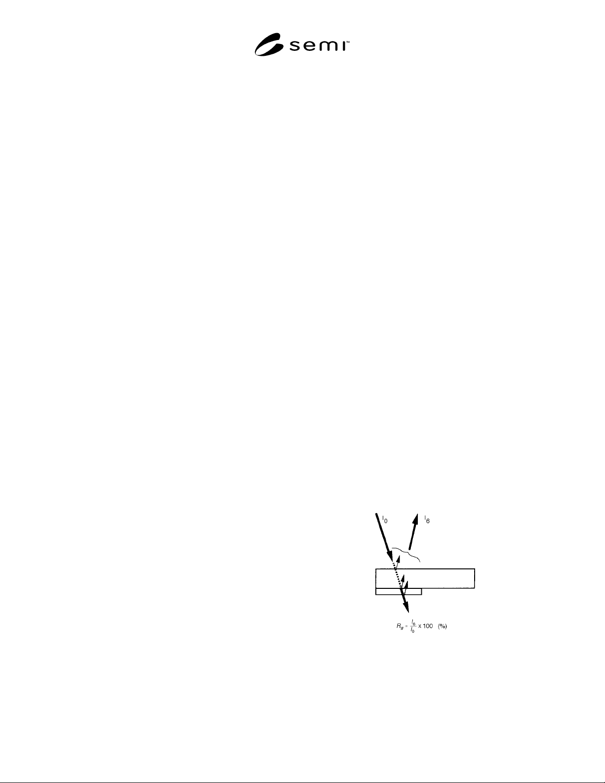
4.3.1 glass side reflectivity — a ratio of intensity of
reflected light to intensity of incident light into the glass
side that is the backside of the shifter film. The
intensity of incident light is usually calculated by the
intensity of reflected light measured using a reference
mirror. (Figure 1 illustrates the glass side reflectivity.)
Figure 1
Glass Side Reflectivity
SEMI P29-0997 © SEMI 1997 2
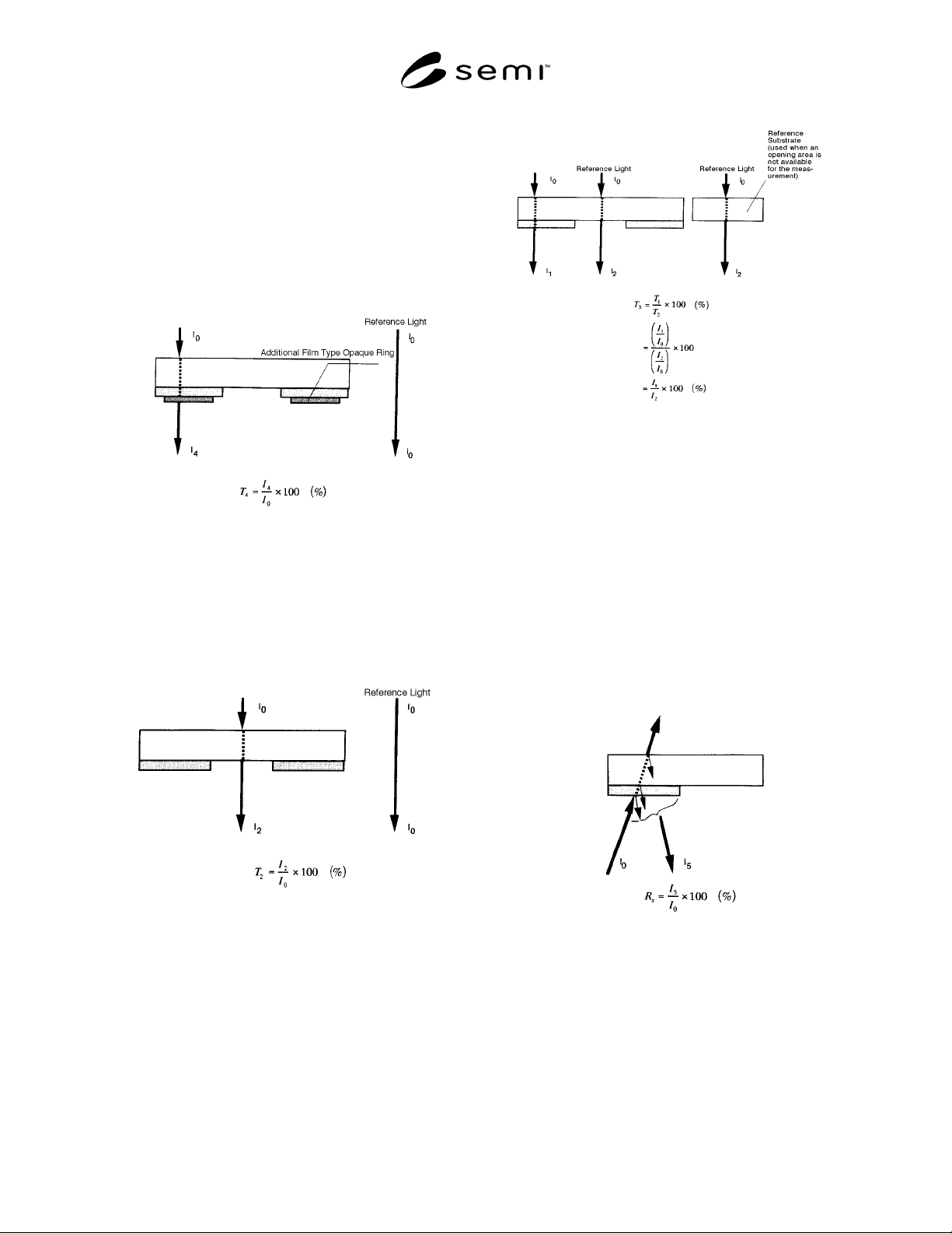
4.3.2 opaque ring transmittance — a ratio of intensity
of light transmitted through the additional film type
opaque ring area to intensity of incident light measured
with air reference. (Figure 2 illustrates the opaque ring
transmittance.)
NOTE 1: For a halftone phase shift mask with embedded
shifter type opaque ring, transmittance of the opaque ring area
is not defined in this guideline because it depends heavily on
the characteristics of the optical systems used.
Figure 2
Opaque Ring Transmittance
4.3.3 opening area transmittance — a ratio of
intensity of light transmitted through an opening area of
a patterned halftone phase shift mask to intensity of
vertical incident light measured with air reference.
(Figure 3 illustrates the opening area transmittance.)
Figure 3
Opening Area Transmittance
4.3.4 phase difference — a difference in phase of light
generated by vertical transmission through a shifter area
and an opening area with air equivalent to the shifter
film in thickness.
4.3.5 relative transmittance — a ratio of intensity of
light transmitted through a shifter area to intensity of
light transmitted through an opening area. (Figure 4
illustrates the relative transmittance.)
Figure 4
Relative Transmittance
4.3.6 shifter side reflectivity — a ratio of intensity of
reflected light to intensity of incident light onto the
surface of a shifter film. The reflected light is the sum
of the reflected light from the shifter surface and
reflected light from the boundary between shifter and
glass, and the boundary between glass and air. The
reflectivity depends on the incident angle, the
wavelength of the light, and the extent of polarization
of the incident light. The intensity of incident light is
usually calculated by the intensity of reflected light
measured using reference mirror. (Figure 5 illustrates
the shifter side reflectivity.)
Figure 5
Shifter Side Reflectivity
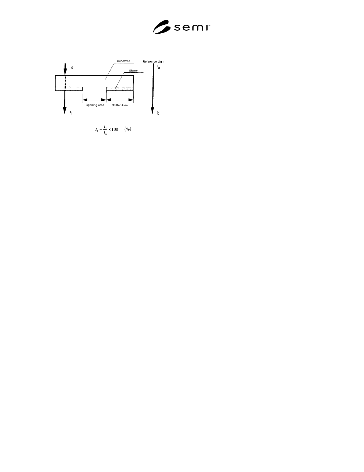
4.3.7 shifter area transmittance — ratio of intensity of
light transmitted through a shifter area of a halftone
phase shift mask (blank) to intensity of vertical incident
light measured with air reference. (Figure 6 illustrates
the shifter transmittance.)
SEMI P29-0997 © SEMI 19973
Figure 6
Shifter Area Transmittance
5 Mask Structure
5.1 Structure of a shifter shall be specified as single-
layer type or multilayer type. A halftone shifter film
whose components gradually change is classified into
the multilayer type.
5.2 Structure of an opaque ring shall be specified as
embedded shifter type or additional film type. In case of
a mask blank, a light shield film may be added or not.
5.3 Addition of an electrically conductive layer, and/or
a thin film for an etch-stop function shall be agreed
upon by the supplier and user.
6 Film Thickness
6.1 For a mask blank, specifications such as film
thickness of a shifter shall be agreed upon by the
supplier and user. The film thickness may be described
using a physical film thickness obtained from step
height measurement, an optical film thickness obtained
from ellipsometry or spectroscopy, and a controlled-
film thickness obtained from rate method. Measuring
method and measuring instrument shall be agreed upon
by the supplier and user.
7 Film Materials
7.1 Specifications for materials and composition per
layer in a shifter film and the opaque ring shall be
agreed upon by the supplier and user.
8 Exposure Wavelength
8.1 As exposure wavelength, the center wavelength of
g-line, i-line, KrF, ArF, and/or DUV shall be described
in nm.
9 Transmittance
9.1 Specifications of transmittance shall be agreed
upon by the supplier and user considering the selection
of terms listed in Section 4.3 of this guideline.
9.2 A relative transmittance can also be obtained from
the ratio of the shifter transmittance to the opening
transmittance of a patterned halftone phase shift mask.
In case the opening is not measurable, or it is a mask
blank, a transmittance of a reference substrate should be
used. The reference substrate shall be agreed upon by
supplier and user beforehand.
9.3 Specifications of opening transmittance shall be
agreed upon by the supplier and user considering its
dependency to etching method.
9.4 Transmittance at the defect inspection wavelength,
the dimension measurement wavelength, and/or the
alignment wavelength shall be agreed upon by the
supplier and user.
10 Phase Difference
10.1 Specifications of phase difference shall be agreed
upon by the supplier and user giving attention to the
measurement method. The unit should be degree. For a
mask blank, the dependency of phase difference of a
processed mask on the process method should be
considered.
10.2 A measurement wavelength should be specified
with its center value in nm. The measurement
instrument and the bandwidth shall be agreed upon by
the supplier and user.
11 Reflectivity
11.1 Shifter side reflectivity and glass side reflectivity
should be described in percent, and its specification
shall be agreed upon by the supplier and user. A
measuring wavelength, a measuring instrument, a
reference mirror, and an incident angle which are used
for measurement shall be agreed upon by the supplier
and user.
11.2 A defect inspection wavelength and an alignment
wavelength shall be agreed upon by the supplier and
user.
12 Opaque Ring Specificatio n
12.1 Specification of an opaque ring shall be agreed
upon by the supplier and user considering the type of
opaque ring.