semi合集-English.pdf - 第6957页
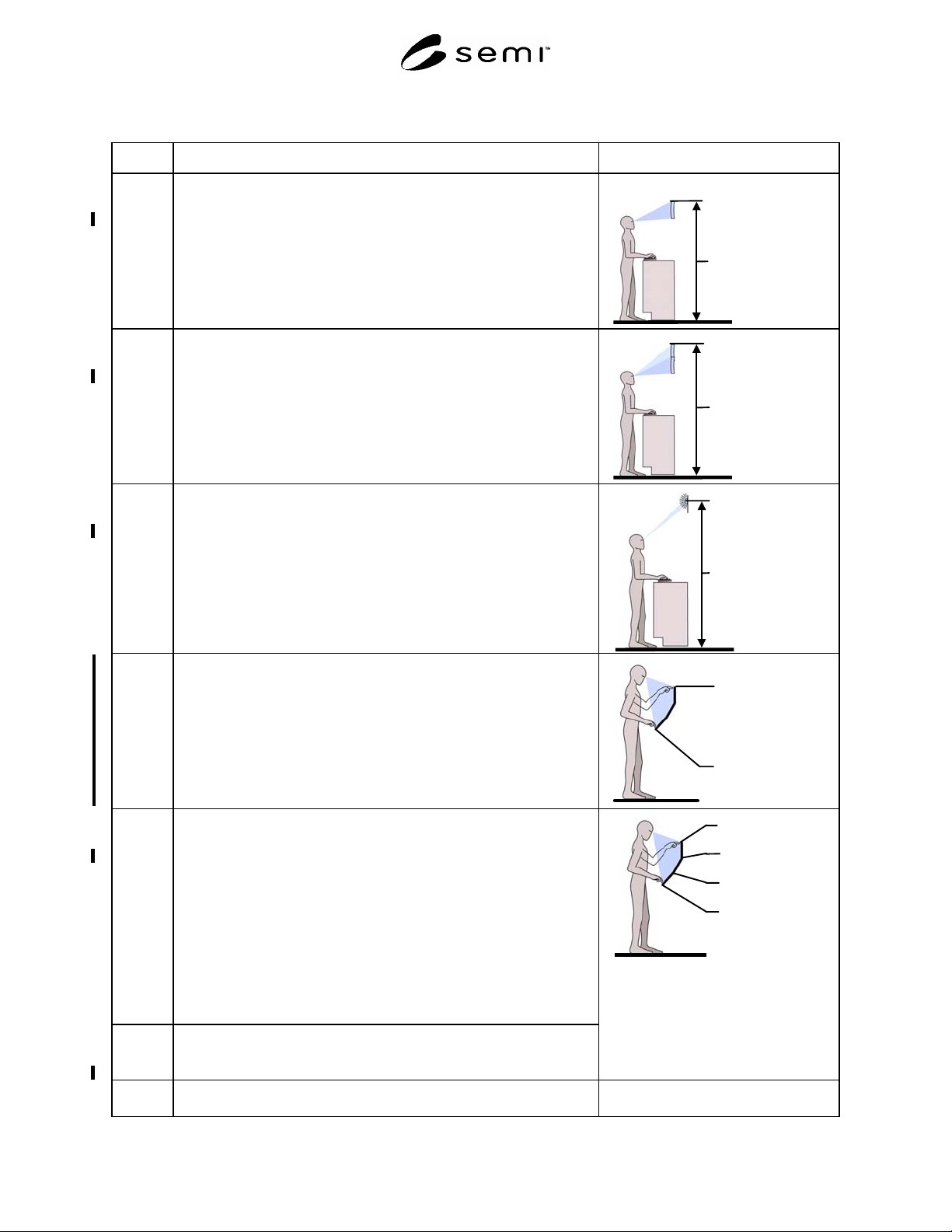
SEMI S8-0705 © SEMI 1995, 2005 54 Section 8: Display Location Section Indicator Figure 8.2.1 Height of video display terminal (single monitor). Does not includ e touchscreens, measured from fl o or to centerline of monit…
SEMI S8-0705 © SEMI 1995, 2005 53
Section 8: Display Location
Section Indicator Figure
8.1.3 Height of infrequently used video display terminal (viewed briefly less
often than once per hour) measured to top line of monitor.
Acceptance criterion: maximum 1680 mm (66 in.)
Infrequently used
monitor
Maximum 1680 mm
(66 in.)
8.1.4 Height of very infrequently used video display terminal (viewed briefly
less often than once per day) measured to top line of monitor.
Acceptance criterion: maximum 1880 mm (74 in.)
Very infrequently
used monitor
Maximum 1880
mm
(74 in.)
8.1.5 Height of infrequently viewed visual signal measured to the top of the
signal. This guideline does not apply to light towers.
Acceptance criterion: maximum 2130 mm (84 in.)
Visual signal height
Maximum 2130 mm
(
84 in.
)
8.1.6 Height of touch screen monitor.
Acceptance criteria: maximum 1470 mm (58 in.), measured from floor
to uppermost active pad on screen
minimum 910 mm (36 in.), measured from floor to
lowest active pad on the screen.
See §9 for horizontal reach criteria.
NOTE: Touch screen design recommendations also apply to light pen
operated systems.
Top of active area
Maximum height
1470 mm (58.0”)
Bottom of active
area
Minimum height
910 mm (36.0”)
8.1.7 Tilt angle of touch screen monitor between 41 and 48 inches in height to
top of screen.
Acceptance criterion: upward minimum 30 degrees
NOTE A: Angle adjustment is recommended to accommodate users of
varying heights and to reduce glare under different lighting
conditions.
NOTE B: The angle of visibility for flat panel display touch screens
varies depending upon which display technology is used
(e.g., passive vs. active matrix) so providing angle
adjustment will allow users to set the display angle for
maximum visibility and comfort.
8.1.8 Tilt angle of touch screen monitor less than 41 inches in height to top of
screen.
Acceptance criterion: upward minimum 45 degrees
0
0
30
0
45
0
1
3
7
0
mm
(
54.0”
)
1220 mm
(48.0”)
1042 cm
(41.0”)
910 mm
(36.0”)
8.2 Location for operator primary interface, seated station (Note: A seated
station where a short cylinder office-style chair is used.)
SEMI S8-0705 © SEMI 1995, 2005 54
Section 8: Display Location
Section Indicator Figure
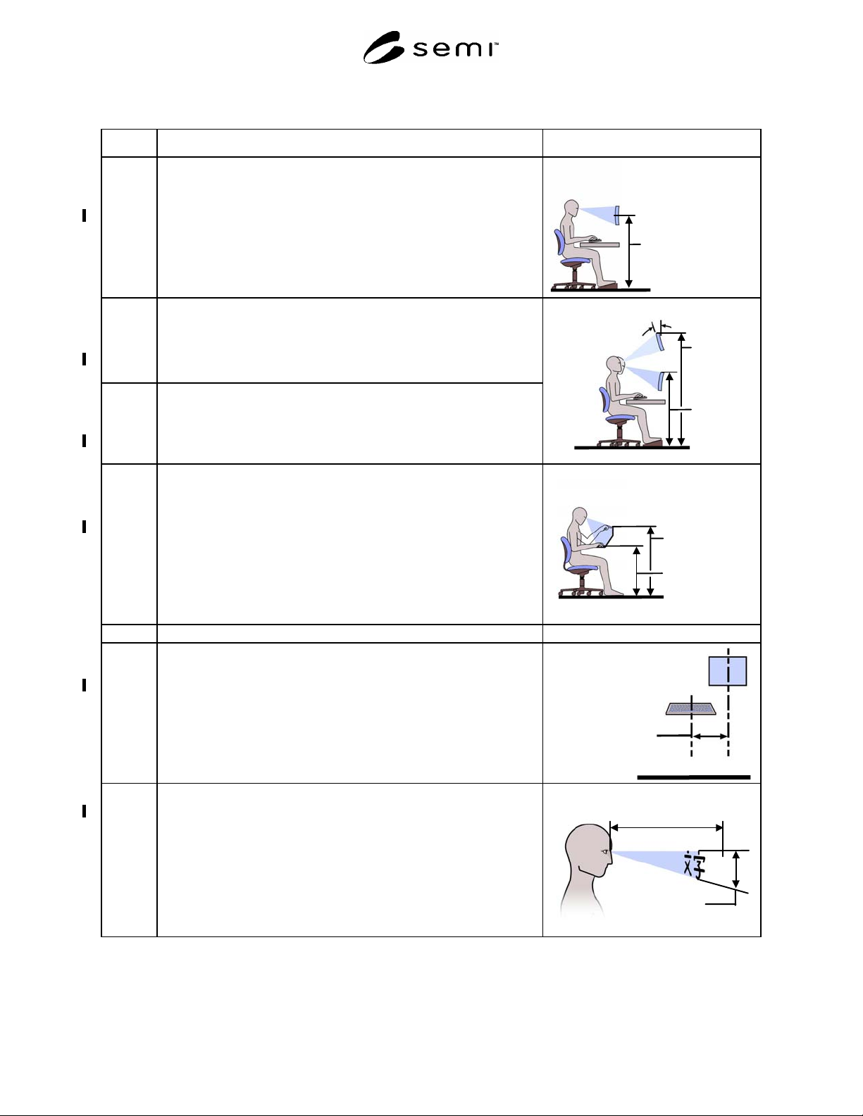
8.2.1 Height of video display terminal (single monitor). Does not include
touchscreens, measured from floor to centerline of monitor.
Acceptance criteria: maximum 1190 mm (47 in.)
minimum 940 mm (37 in.)
NOTE A: The display user should be able to view a display while
maintaining a near-neutral posture.
Display height
Maximum 1190 mm
(47 in.)
Minimum 940 mm
(37 in.)
8.2.2 Height of video display terminal (stacked monitors), does not include
touchscreens, measured from floor to top line of top monitor.
Acceptance criteria: maximum 1400 mm (55 in.)
minimum 940 mm (37 in.)
The primary monitor in a stacked configuration is the bottom monitor.
8.2.3 Tilt angle of video display terminal greater than 55 inches in height to top
of screen. This line item becomes significant in the event that the
maximum height criteria cannot be met.
Acceptance criterion: downward minimum 15 degrees
Minimum
height
940 mm
(37 in.)
Maximum
height
1400 mm
(55 in.)
Downward tilt of
top monitor
Minimum 15
0
8.2.4 Height of touch screen monitor
Acceptance criteria: maximum 1070 mm (42 in.) measured from floor to
highest active pad on the screen
minimum 760 mm (30 in.) measured from floor to
lowest active pad on the screen
See §9 for horizontal reach criteria.
NOTE: Touch screen design recommendations also apply to light
pen operated systems.
Active touch
pad area
Minimum 760
mm
(30 in.)
Maximum 1070
mm
(42 in.)
8.3 Display characteristics
8.3.1 Lateral distance from the centerline of the display to the centerline of the
input device(s).
Acceptance criterion: maximum 320 mm (12.6 in.)
NOTE: If several input devices are used (i.e. keyboard and mouse)
the centerline of the input device farthest from the display
should be measured.
Lateral distance
between monitor
and input device
Maximum 320 mm
(12.6 in.)
8.3.2 Character height (Specific to Chinese, Korean and Japanese characters.)
Acceptance criterion: character height is greater than or equal to the
viewing distance divided by 143
Recommended viewing distance is between 457 mm (18 in.) and 762 mm
(30 in.).
Viewing distance 457-
762 mm
(18-30 in.)
Character height =
viewing distance
divided by 143
SEMI S8-0705 © SEMI 1995, 2005 55
Section 8: Display Location
Section Indicator Figure
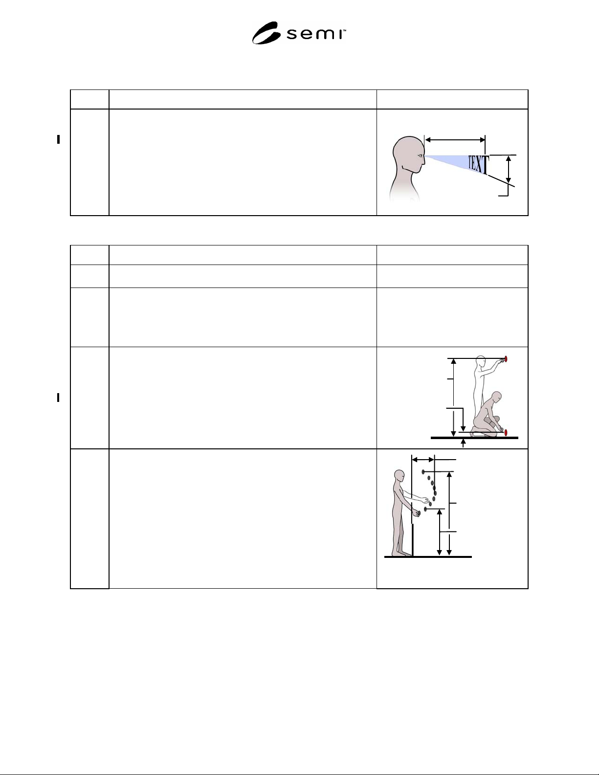
8.3.3 Character height (All characters other than Chinese, Korean and
Japanese.)
Acceptance criterion: character height is greater than or equal to the
viewing distance divided by 215
Recommended viewing distance is between 457 mm (18 in.) and 762 mm
(30 in.).
Viewing distance 457-
762 mm
(18-30 in.)
Character height =
viewing distance
divided by 143
Section 9: Hand Control Location
Section Indicator Figure
9.0 Hand Control Location (These criteria only apply to controls, tools, and
materials accessed for routine production operation and maintenance.)
9.1 Standing station
NOTE: A standing station is one where the machine operator can
assume a standing posture or a seated posture in a tall stool,
which places the operator at approximately the same stature.
9.1.1 Vertical location of very infrequently used controls (controls used less
often than once every 24 hours) measured from the standing surface to the
centerline of the control.
Acceptance criteria: maximum 1640 mm (64.5 in.).
minimum 0 mm (0 in.).
Minimum 0 mm
(0 in.)
Maximum 1640
mm
(64.5 in.)
9.1.2 Location of infrequently used and/or critical controls. Maximum reaches
are indicated for various heights. Reaches are measured from the leading
edge of the equipment or obstacle.
Acceptance criteria: controls should not be located above 1638 mm (64.5
in.) or below 838 mm (33 in.).
NOTE A: Interpolate for intermediate values.
NOTE B: Reach distances should be measured from the leading edge of
the machine housing or obstructions between the machine
operator and the control. Obstructions include keyboard trays,
drip trays, machine anti-vibration pads and load-bearing pads.
NOTE C: See Figure 9.1.2 for maximum recommended reaches.
Minimum 838
mm
(33 in.)
Maximum 483
mm
(19 in.)
Maximum 1638
mm
(64.5 in.)