semi合集-English.pdf - 第6241页
SEMI G47-88 © SEMI 1988 8 Detail C Gate Relief Table 4 Lead C ount 52 68 84 100 132 164 196 244 f 0.435 0.4 8 5 0.535 0.585 0.685 0.785 0.885 T. B.D. g 0.394 0.444 0.494 0.544 0.6 44 0.744 0.8 44 T.B.D. h 0.360 0.410 0.4…
SEMI G47-88 © SEMI 19887
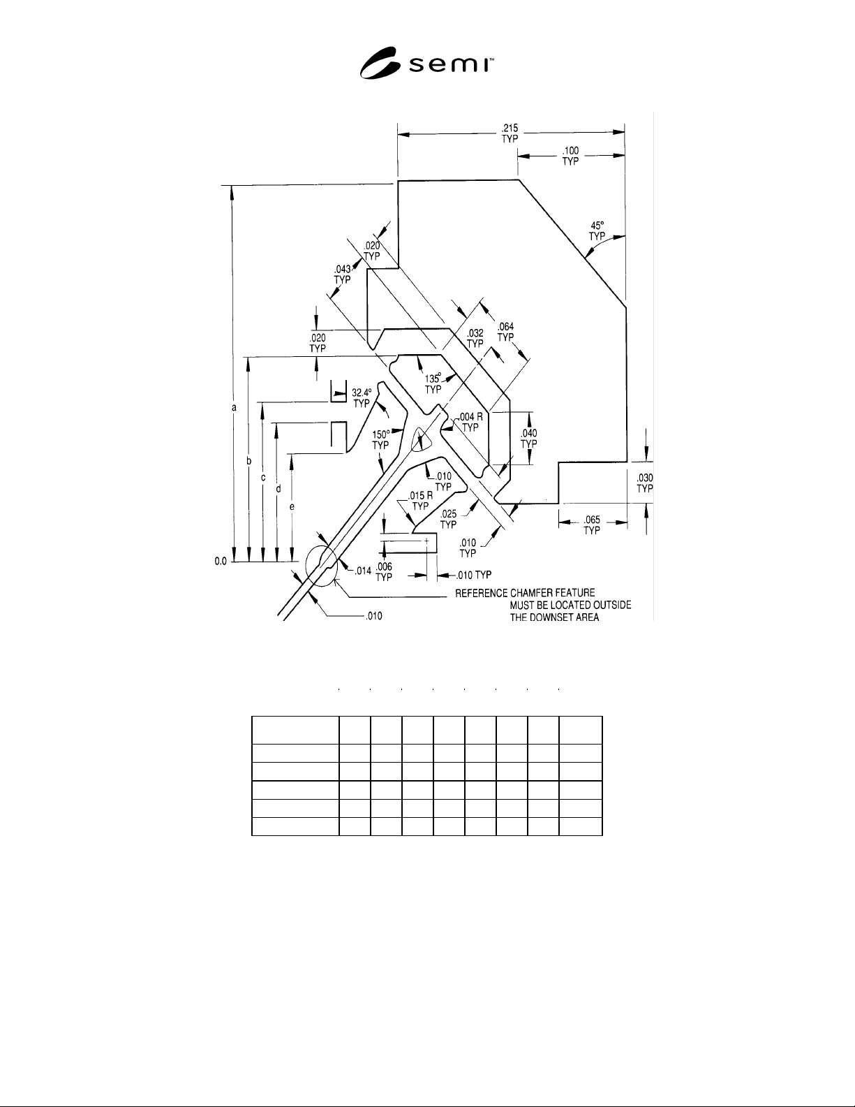
Detail B
Bumper/Tie Bar and Relief
Table 3
Leadcount 52 68 84 100 132 164 196 244
a 0.435 0.485 0.535 0.585 0.685 0.785 0.885 T.B.D.
b 0.305 0.355 0.405 0.455 0.555 0.655 0.755 T.B.D.
c 0.270 0.320 0.370 0.420 0.520 0.620 0.720 T.B.D.
d 0.255 0.305 0.355 0.405 0.505 0.605 0.705 T.B.D.
e 0.231 0.281 0.331 0.381 0.481 0.581 0.681 T.B.D.
SEMI G47-88 © SEMI 1988 8
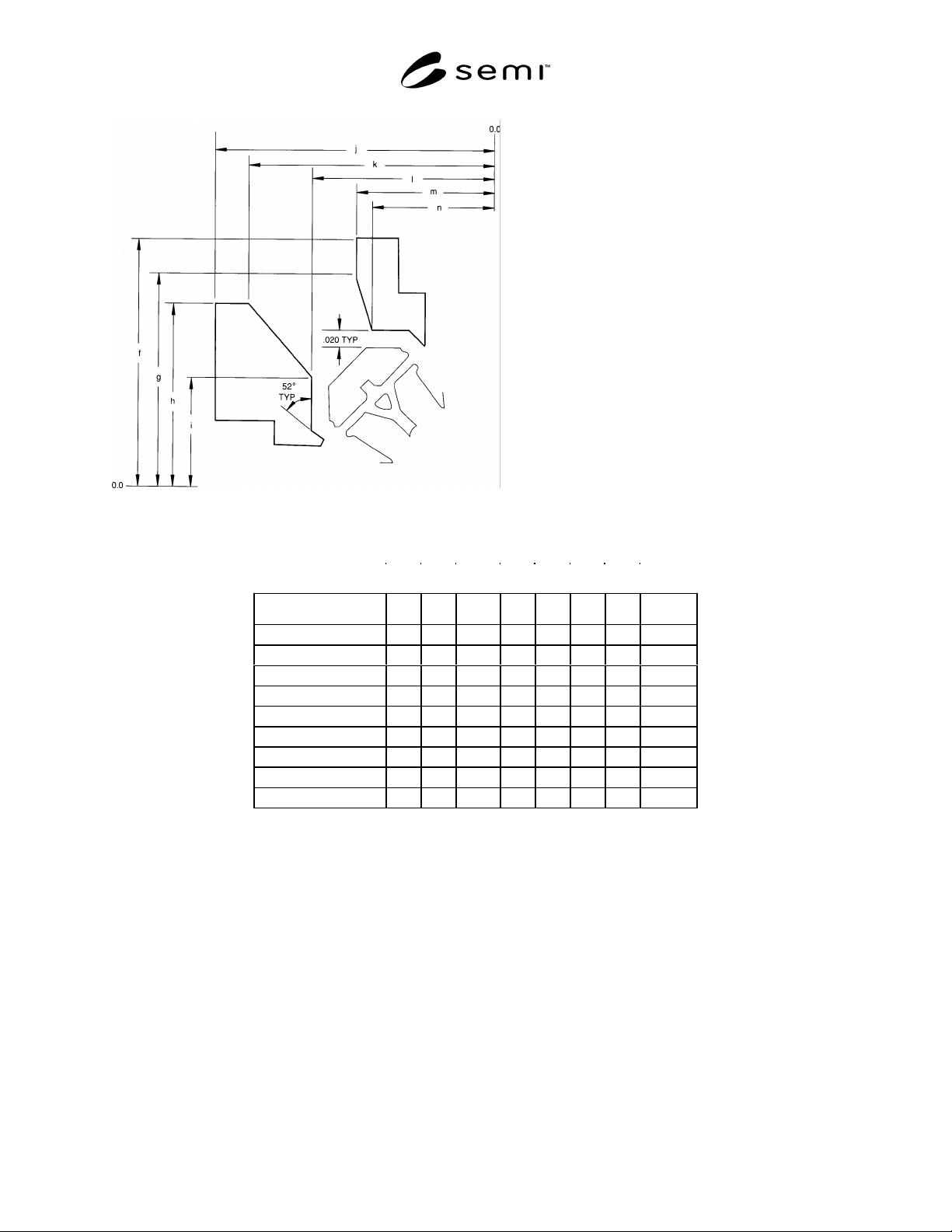
Detail C Gate Relief
Table 4
Lead Count 52 68 84 100 132 164 196 244
f 0.435 0.485 0.535 0.585 0.685 0.785 0.885 T.B.D.
g 0.394 0.444 0.494 0.544 0.644 0.744 0.844 T.B.D.
h 0.360 0.410 0.460 0.510 0.610 0.710 0.810 T.B.D.
i 0.272 0.322 0.372 0.422 0.522 0.622 0.722 T.B.D.
j 0.435 0.485 0.535 0.585 0.685 0.785 0.885 T.B.D.
k 0.399 0.449 0.499 0.549 0.649 0.749 0.849 T.B.D.
l 0.325 0.375 0.4325 0.475 0.575 0.675 0.775 T.B.D.
m 0.269 0.319 0.369 0.419 0.519 0.619 0.719 T.B.D.
n 0.253 0.303 0.353 0.403 0.503 0.603 0.703 T.B.D.
SEMI G47-88 © SEMI 19889
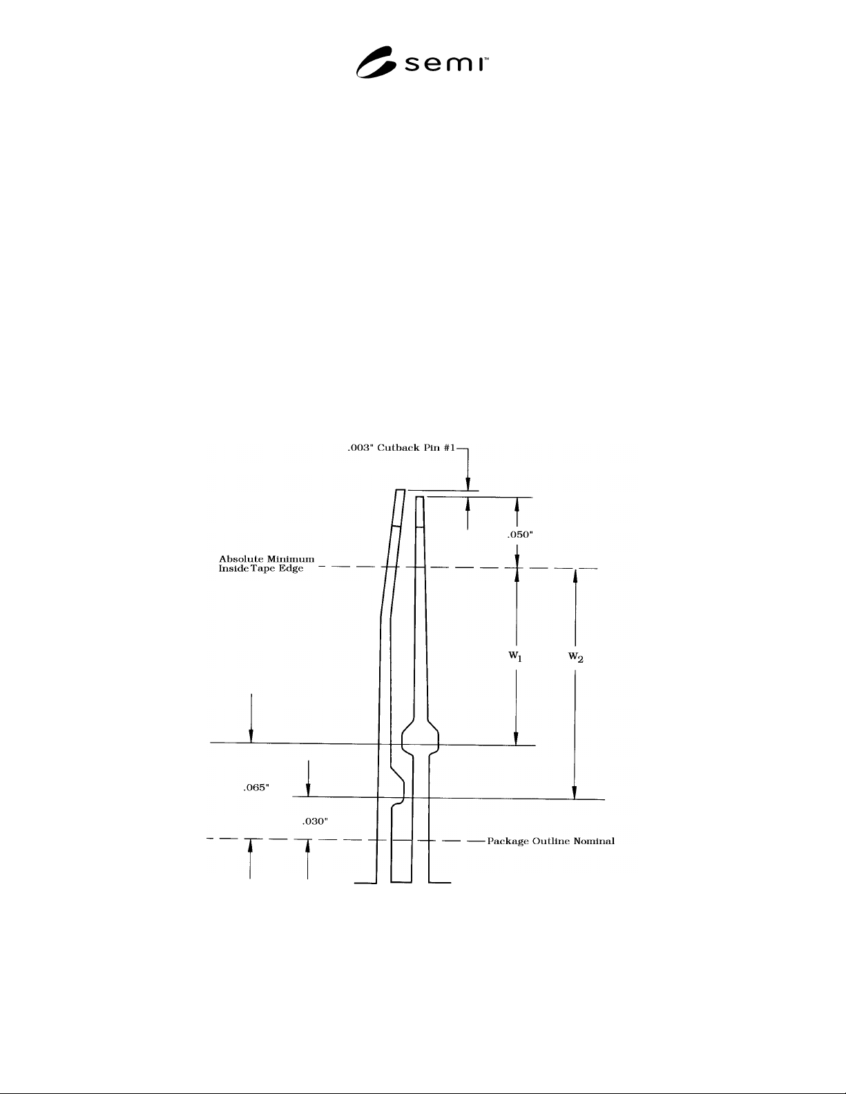
Table 4 (see Figure 7) Guidelines for Placement of Taping Dimensions 84 Lead Through 196 Leadframes
1. Nominal tape width maximum — 0.037"
2. Nominal tape width maximum — 0.060"
3. Tape width tolerance — ± 0.003"
4. Tape location tolerance — ± 0.015"
5. Absolute minimum location of outside tape edge from lead tip — 0.050".
6. Minimum location of outside tape edge from package outline nominal dimension — 0.065".
7. When window “W1” dimension cannot be met with minimum tape nominal width and recommended tolerancing
which is the case with various given pad sizes of different lead counts, window “W2” dimension, 0.030", from
package outline nominal should be used for the outside tape limit. If this window “W2” dimension still cannot be
met negotiation of tape width and location tolerances between supplier and purchaser is suggested to maintain
tape within the recommended window dimensions.
8. Recommended center line of tape for nominal location is midway between inside and outside tape edge limits for
window “W1” & window “W2” dimensions as appropriate and within tolerance limits.
9. Downset angle — 30°
10.Downsetting must begin inside 0.025" minimum flat distance along tie bar from inside edge of applied tape.
11.Recommended downset length is maximum allowable within the above guidelines.
Figure 7