semi合集-English.pdf - 第4863页
SEMI M1-0305 © SEMI 1978, 2005 39 Position 3: Reference Plane and Area (I ), (3), (L), (Q), or (S), and Position 4: Measurement Parameter (R) or (D). A1-2.7.1 Stat ing this code, t he numerical values for the FQA par…
SEMI M1-0305 © SEMI 1978, 2005 38
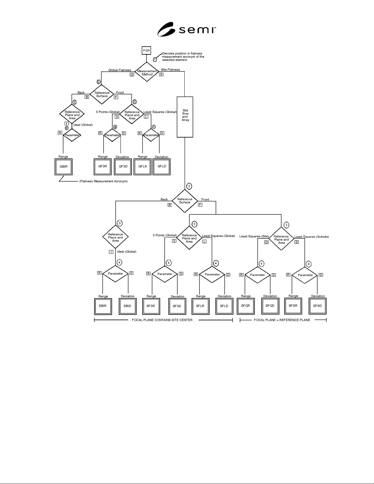
Figure A1-1
Flatness Decision Tree
A1-2.5.2 For site flatness measurements, any of the above three planes [(1), (3), or (L)] may be suitable or, if the
wafer is regimballed once at each site, a site least squares reference plane (Q) may be appropriate or, if the wafer is
regimballed more than once at each site, a subsite least squares reference plane (S) may be appropriate.
A1-2.6 Step 5 — Choose the Measurement Parameter: Choose either TIR, also known as range (R), or FPD, also
known as deviation (D). In the case of site measurements, it is possible to specify the maximum value of (R) or (D)
or the percentage of the sites (or FQA) which have an (R) or (D) less than some specified value.
A1-2.7 The codes in parentheses in Steps 2 through 5 may be used to form a code which uniquely defines the
measurement technique as follows:
Position 1: Measurement Method (G) or (S),
Position 2: Reference Surface (F) or (B),
SEMI M1-0305 © SEMI 1978, 2005 39
Position 3: Reference Plane and Area (I), (3), (L), (Q), or (S), and
Position 4: Measurement Parameter (R) or (D).
A1-2.7.1 Stating this code, the numerical values for the FQA parameters (and, if required, information on site size
and array), and the numerical limit for the measurement parameter provides enough information to describe the
measurement and provide numerical limits.
A1-3 Future Developments
A1-3.1 As noted above, there may be specific systems which are not exactly described by one of the branch ends on
this decision tree. This tree is an approximation of the more complete one which would describe all existing and
possible lithographic technologies.
Lss
Wss = 8 mm
Subsite
Site
Scan Direction = Y
Lss
Wss
FQA
Site Center
Subsite Center
Site
Subsite area
within FQA
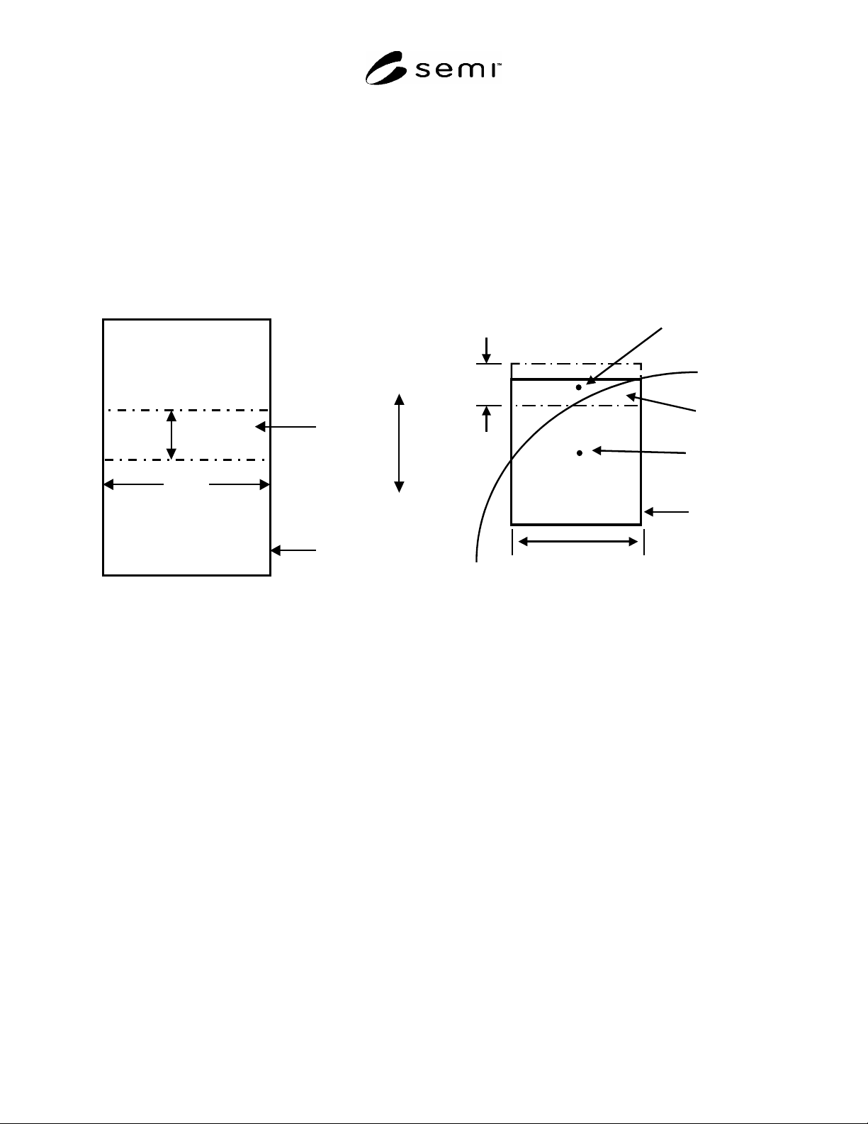
Figure A1-2
Scanner Site and Subsite Flatness Elements
Figure A1-3
Subsite Center near Boundaries of Site and FQA

SEMI M1-0305 © SEMI 1978, 2005 40
APPENDIX 2
SHAPE DECISION TREE
NOTICE: The material in this appendix is an official part of M1. Approval was by full letter ballot procedures with
publication authorized by the NA Regional Standards Committee on October 21, 1999.
A2-1 Scope
A2-1.1 In modern wafer fabrication processes, wafer surface geometry in the unclamped state can be a sensitive
indicator of process effects. Larger wafer diameters and increasing complexity of processes and circuits have
increased the need for accurate, standardized measurement of unclamped wafer geometry. The quantities that have
historically been used, Bow and Back Surface Referenced Warp, may be inadequate to describe and quantify the
geometries of interest in advanced processes. Additional surface geometry quantities, such as Sori and Median
Surface Referenced Warp, have been introduced into standards.
A2-1.2 In addition, there is considerable confusion as to the precise meaning of these quantities, even though they
are defined in the applicable SEMI test methods.
A2-1.3 The Shape Decision Tree was developed to provide an orderly method of identifying each of the variables
involved in the quantities used to quantify unclamped wafer surface geometry. As such, the tree provides a concise
and precise description of each shape quantity. A branch of the tree consists of a selection of one of the choices for
each variable. The variables and the choices for each are listed in Table A1-1.
A2-1.4 Four branches of the tree, representing quantities for which measurement methods have been standardized
by SEMI, are depicted in Figure A1-1. There are many other branches of the tree, not all of which may represent
practical combinations of variables.
A2-2 Use of the Shape Decision Tree
A2-2.1 Step 1. Select the Fixed Quality Area (FQA): Decide on and specify the nominal edge exclusion, EE, which
defines the FQA. (See Figure 1.)
A2-2.2 Step 2. Select the measurement method: global (over the entire fixed quality area) or local (over a site).
NOTE 1: At present, all shape quantities in common use are global measurements. The significance and use of local shape
quantities have yet to be defined.
A2-2.3 Step 3. Select the reference surface: front, median, or back, to be used to establish the reference plane.
A2-2.4 Step 4. Select the kind of reference plane: least-squares or 3-point.
NOTE 2: A measurement made with a least-squares reference plane is less affected by small changes in wafer position within
the measurement apparatus than is a measurement made with a 3-point reference plane.
A2-2.5 Step 5. Determine whether the effects of gravitational sag on the wafer are accounted for (yes) or not (no).
NOTE 3: Gravitational effects may be accounted for by inverting the wafer during the measurement, by placing the wafer in a
vertical or nearly vertical position during the measurement, or mathematically.
A2-2.6 Step 6. Select the measurement surface: front, median, or back, for which the deviations are to be
measured.
A2-2.7 Step 7. Select the measurement pattern: full scan (a regular array of measurement points over the entire
measurement area), partial scan (a specified pattern of measurement points covering only a portion of the
measurement area), or centerpoint (measurement at the center of the wafer only).
A2-2.8 Step 8. Select the parameter to be determined: range (TIR) or maximum RPD.
A2-2.9 Step 9. Compare the branch thus obtained with the branches in Figure A2-1. If the branch obtained
matches one of the branches illustrated in Figure A1-1, the resulting quantity is given by the code shown in the box
at the bottom of the branch. Standard test methods have been adopted for measurement of each of these quantities.
If the branch obtained does not match any of the branches illustrated in Figure A2-1, the quantity obtained has not
been given a standardized term, nor has a standard test method been adopted for its measurement.