semi合集-English.pdf - 第3978页
SEMI F42-0600 © SEMI 199 9, 2000 10 13 Related Do cuments 13.1 IEC Standard 2 13.1.1 IEC 61000-4-11 — Electroma g n e tic Compatibility (EMC) - Part 4: Testing and Measuring Techniques - Secti on 11: Voltag e Dips, Sh or…
SEMI F42-0600 © SEMI 1999, 20009
0
10
20
30
40
50
60
70
80
90
0 102030405060
Seconds
%Vnom
Van
Vbn
Vcn
Spec
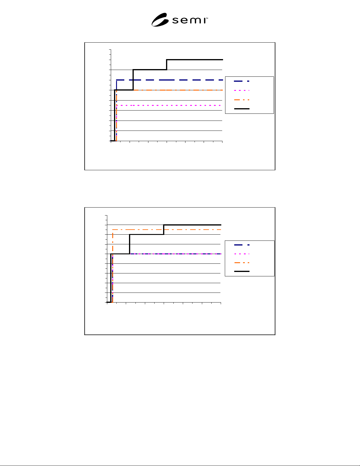
NOTE: Equipment did not meet standard during A to neutral sag events.
Figure 4
Example of Single-Phase Test Results
0
10
20
30
40
50
60
70
80
90
0 102030405060
Seconds
%Vnom
Vab
Vbc
Vac
Spec
NOTE: Equipment did not meet specification during A-C to sag events.
Figure 5
Example of Phase-to-Phase Test Results

SEMI F42-0600 © SEMI 1999, 2000 10
13 Related Documents
13.1 IEC Standard
2
13.1.1 IEC 61000-4-11 — Electromagnetic
Compatibility (EMC) - Part 4: Testing and Measuring
Techniques - Section 11: Voltage Dips, Short
Interruptions and Voltage Variations Immunity Tests.
NOTICE: SEMI makes no warranties or
representations as to the suitability of the test method
set forth herein for any particular application. The
determination of the suitability of the test method is
solely the responsibility of the user. Users are
cautioned to refer to manufacturer’s instructions,
product labels, product data sheets, and other relevant
literature respecting any materials mentioned herein.
These test methods are subject to change without
notice.
The user’s attention is called to the possibility that
compliance with this test method may require use of
copyrighted material or of an invention covered by
patent rights. By publication of this test method, SEMI
takes no position respecting the validity of any patent
rights or copyrights asserted in connection with any
item mentioned in this test method. Users of this test
method are expressly advised that determination of any
such patent rights or copyrights, and the risk of
infringement of such rights, are entirely their own
responsibility.
2 International Electrotechnical Commission, 3, rue de Varembé PO
Box 131, 1211 Geneva 20 Switzerland
SEMI F42-0600 © SEMI 1999, 200011
RELATED INFORMATION 1
SAG GENERATORS
NOTE: This related information is not an official part of SEMI F42 and has been derived from the work of the originating task
force. This related information was approved for publication by full letter ballot procedures on December 18, 1998.
Determination of the suitability of the material is solely the responsibility of the user.
R1-1 Types of Sag Generators
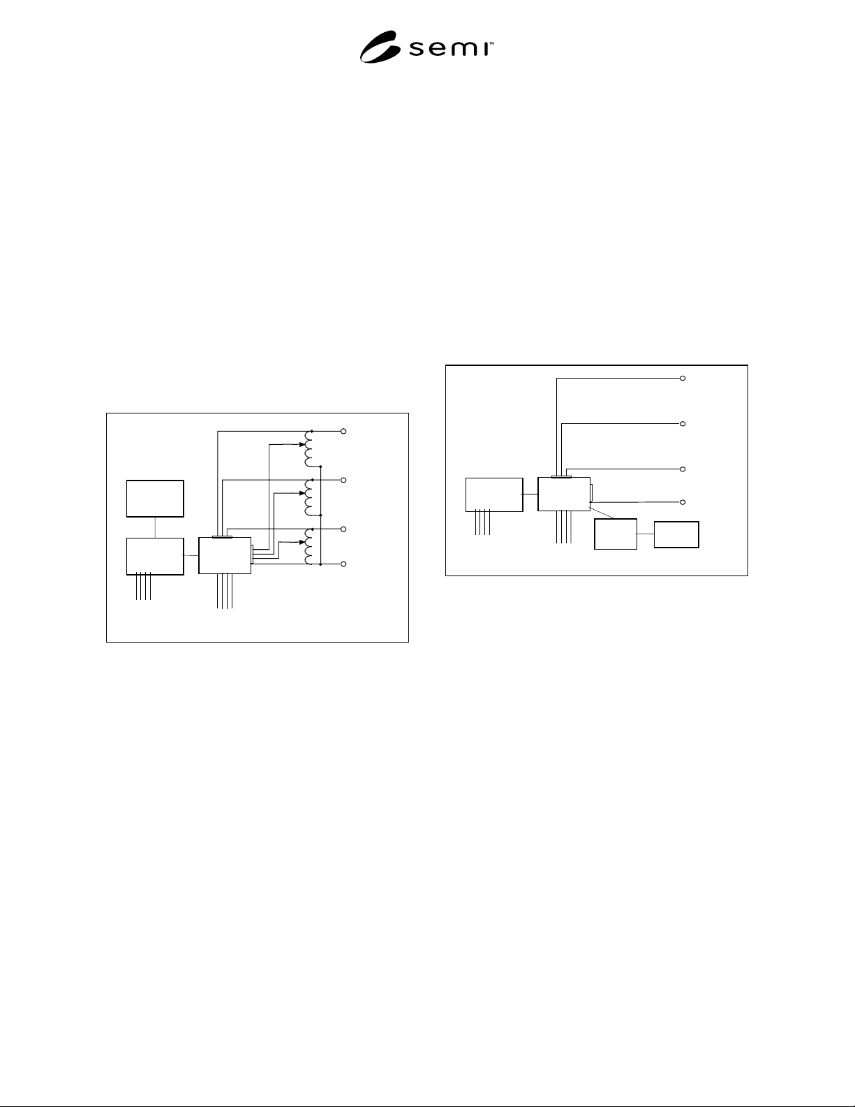
R1-1.1 As defined in the test instrumentation section of
IEC-61000-4-11, there are two common types of
voltage sag generator devices – variable transformer-
switch type and the power amplifier type.
R1-1.2 Both units shown in this section can inject
phase-shifting into the output waveform. All units
except the contactor based transformer-switch type are
capable of some point-on-wave controllability.
Controlle
r
Data Acquisition
And Digital I/O
Solid-state
switches or
contactors
Three-phase
output to load
Nominal
Inpu
t
Variac
Input
Channels
connected
to loa
d
Phase
A
Phase B
Phase
C
N
eutral
Three-phase
utility voltage
Figure R1-1
Transformer-Switch Type Sag Generator
R1-2 Transformer-Switch Type
R1-2.1 This type of sag generator has been built with
either insulated gate bipolar transistor (IGBT), silicon
control rectifier (SCR), or contactors used as the
switching devices. The IGBT based switch is the most
controllable with the ability to precisely control the
point on the waveform in which the voltage sag starts
and finishes (0-360 degrees). With an SCR switch, the
point on wave of the voltage sag starts can be
controlled, but the cutoff point of the voltage sag will
be fixed at zero degrees. In real power systems, the
point-on-wave in which the voltage sag occurs is
somewhat random and unpredictable. A contactor
based unit simulates the randomness of a real power
system in that the point-on-wave in which the voltage
sag begins is not controllable, but is dependent on the
lag time between energizing the coil of the contactor
and contactor closure. Figure R1-1 below displays a
three-phase sag generator test fixture with data
acquisition.
R1-2.2 As shown in Figure R1-1, voltage sags are
injected into the load referenced to the neutral. Since
the three variable transformers shown only need to
carry current during the voltage sag, they do not need to
be rated for continuous current.
Controlle
r
Data Acquisition
& Digital I/O
Power
Amplifier
Three- phase
output to load
Nominal
Input
Channels
connected
to load
Phase
A
Phase B
Phase C
Neutral
Three-phase
Utility voltage
Waveform
Generator
Figure R1-2
Power Amplifier Type Sag Generator
R1-3 Power Amplifier Type
R1-3.1 This type of system utilizes a controller, wave-
form generator, data acquisition systems, and power
amplifier section. Since this type of amplifier can be
highly configurable, it can simulate most any point-on-
wave or phase-shift desired. The power amplifier-
based sag generator will be typically heavier and less
portable than its transformer-switch counterpart. A
conceptual three-phase version of this type of sag
generator test fixture is shown in Figure R1-2.
NOTICE: SEMI makes no warranties or
representations as to the suitability of the test method
set forth herein for any particular application. The
determination of the suitability of the test method is
solely the responsibility of the user. Users are
cautioned to refer to manufacturer’s instructions,
product labels, product data sheets, and other relevant
literature respecting any materials mentioned herein.
These test methods are subject to change without
notice.