semi合集-English.pdf - 第132页
1. Th e percent of full scale change in output will no t exceed a specified value for a ny value of temperature within a specified temperature range . Example: “± 1.5% of full scale m aximum error over 10°C to 50°C” 2. I…
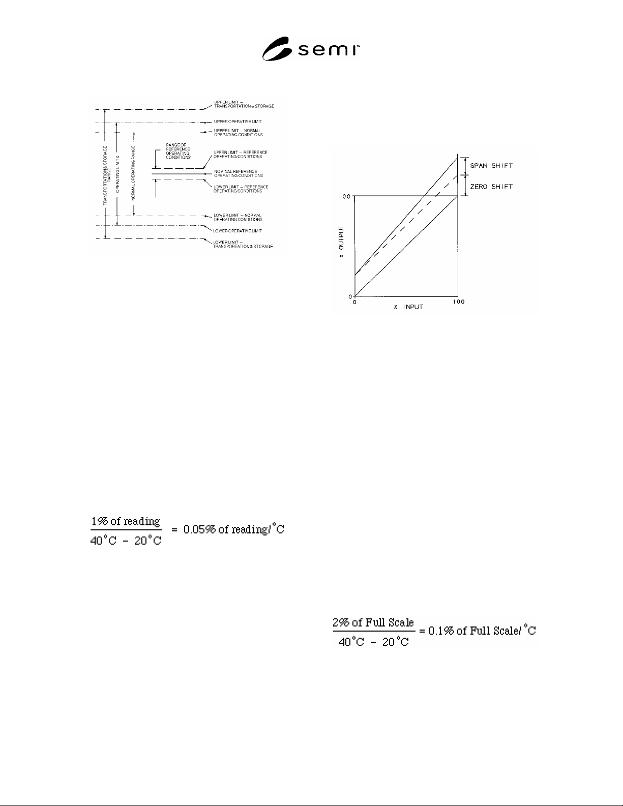
4.1.9.1 Description form: ___°C – ___°C
Figure 1
4.1.10 temperature effects — See Figure 2.
NOTE 2: This section requires that Gas Temperature be the
same as Ambient Temperature.
4.1.10.1 span effect — the change in span due to a
change in ambient temperature from one normal
operating temperature to a second normal operating
temperature. All other conditions must be held within
the limits of reference operating conditions.
4.1.10.1.1 The effect of temperature change on span
may be expressed as a coefficient calculated as the ratio
of percent of reading change in output to the
corresponding change in temperature. The change in
ambient temperature should be specified. This
coefficient is defined as the “temperature coefficient of
span.”
Example: Temperature coefficient of span may be
expressed as:
NOTE 3: If the relation between temperature and change in
output is linear, one coefficient will suffice.
4.1.10.1.2 If the temperature influence is non-linear a
different method of expression may be used. Two
examples:
1. The percent of span change in output will not
exceed a specified value for any value of
temperature within a specified temperature range.
Example: “± 1.0% of reading maximum error over
10°C to 50°C”
2. It may be desirable to state a series of coefficients
for successive increments of temperature within a
specified temperature range.
Figure 2
Span and Zero Shift
4.1.10.2 total effect — the change in output, including
zero and span, due to a change in Ambient Temperature
from one normal operating temperature to a second
normal operating temperature. All other conditions
must be held within the limits of reference operating
conditions.
4.1.10.3 zero effect — the change in zero due to a
change in ambient temperature from one normal
operating temperature to a second normal operating
temperature. All other conditions must be held within
the limits of reference operating conditions.
4.1.10.3.1 The effect of temperature change on zero
may be expressed as a coefficient calculated as the ratio
of full scale percent change in output to the
corresponding change in temperature. The change in
ambient temperature should be specified. This
coefficient is defined as the “temperature coefficient of
zero.”
Example: Temperature coefficient of zero may be
expressed as:
NOTE 4: If the relation between temperature and change in
output is linear, one coefficient will suffice.
4.1.10.3.2 If the temperature influence is non-linear a
different method of expression may be used. Two
examples:
SEMI E18-91 © SEMI 1991, 2004 2

1. The percent of full scale change in output will not
exceed a specified value for any value of
temperature within a specified temperature range.
Example: “± 1.5% of full scale maximum error over
10°C to 50°C”
2. It may be desirable to state a series of coefficients
for successive increments of temperature within a
specified temperature range.
4.1.11 units — degrees Celsius (C) is used as the
temperature unit.
NOTICE: SEMI makes no warranties or
representations as to the suitability of the standards set
forth herein for any particular application. The
determination of the suitability of the standard is solely
the responsibility of the user. Users are cautioned to
refer to manufacturer's instructions, product labels,
product data sheets, and other relevant literature,
respecting any materials or equipment mentioned
herein. These standards are subject to change without
notice.
By publication of this standard, Semiconductor
Equipment and Materials International (SEMI) takes no
position respecting the validity of any patent rights or
copyrights asserted in connection with any items
mentioned in this standard. Users of this standard are
expressly advised that determination of any such patent
rights or copyrights, and the risk of infringement of
such rights are entirely their own responsibility.
Copyright by SEMI® (Semiconductor Equipment and Materials
International), 3081 Zanker Road, San Jose, CA 95134. Reproduction of
the contents in whole or in part is forbidden without express written
consent of SEMI.
SEMI E18-91 © SEMI 1991, 2004 3

SEMI E19-0697 © SEMI 1991, 2002 1
SEMI E19-0697 (Reapproved 0702)
STANDARD MECHANICAL INTERFACE (SMIF)
This standard was technically approved by the Global Physical Interfaces & Carriers Committee and is the
direct responsibility of the North American Physical Interfaces & Carriers Committee. Current edition
approved by the North American Regional Standards Committee on March 17, 2002. Initially available at
www.semi.org June 2002, to be published July 2002. Originally published in 1991; previously published June
1997.
NOTE: This standard has been purposely restricted to 100
mm (4 in.), 125 mm (5 in.), and 150 mm (6 in.) versions of
the SMIF port. This has been done to establish a base for
SMIF port standardization. Aspects of the 200 mm (8 in.)
version have been negotiated by interested parties and
published as SEMI E19.4.
1 Purpose
1.1 A standard interface is required for containers
intended to control the transport environment of
cassettes containing wafers or disks. The interface must
address the proper container orientation for material
transfer and maintain continuity between the container
and equipment environment in order to control
particulate matter.
2 Scope
2.1 This specification describes one approach to
interfacing a clean cassette transport box to a clean
environmental housing on a piece of semiconductor
processing equipment or to other clean environments.
The system concept involves mating a door on a
cassette container to a door on an equipment canopy
and transferring the cassette into, and out of, the
equipment without exposing the cassette and wafers to
outside contamination.
2.2 This standard does not purport to address safety
issues, if any, associated with its use. It is the
responsibility of the users of this standard to establish
appropriate safety health practices and determine the
applicability or regulatory limitations prior to use.
3 Impact
3.1 The incorporation of this standard requires
equipment designers to include the features of the
interface into the tool design. Spacing between open
cassette ports is inadequate for incorporation of this
interface. Designers are directed to the
recommendations made in SEMI E15 in this regard.
4 Limitations
4.1 This standard is specific to the size of the
designated wafer and references the appropriate SEMI
cassette and wafer diameter. A single numerical suffix
is assigned to this base standard number or each wafer
diameter. This specification focuses on applications in
which the interface port is positioned horizontally. The
standard is focused exclusively on the box-to-canopy
interface. Other considerations of box and equipment
design are purposely excluded.
NOTE 1: Hewlett-Packard has stated that it is seeking patent
coverage for this design and is offering non-exclusive licenses
on an equal basis to any company. Companies intending to
manufacture products to this standard should be aware of
Hewlett-Packard’s position.
NOTE 2: The user’s attention is called to the possibility that
compliance with this standard may require use of an invention
covered by patent rights. By publication of this standard,
Semiconductor Equipment and Materials International
(SEMI) takes no position with respect to the validity of any
patent rights asserted in connection with any item mentioned
in this document. Users of this document are expressly
advised that determination of any such patent rights and the
risk of infringement of such rights are entirely their own
responsibility.
5 Referenced Standards
5.1 SEMI Standards
SEMI E1 — Specification for 3 inch, 100 mm, 125
mm, and 150 mm Plastic and Metal Wafer Carriers
SEMI E15 — Specification for Tool Load Port
6 Terminology
(See Figure 1 for a pictorial depiction of most terms.)
6.1 Definitions
6.1.1 box — an environmentally controlled enclosure
for a cassette containing wafers or disks. For purposes
of this standard, a box has features that conform to the
specified interface. A box includes a box door and box
latches. (A box is also referred to as a container.)
6.1.2 box door — a removable bottom for the box that
contains a means (such as registration holes) for
properly positioning the wafer cassette.
6.1.3 box latches — mechanical latches that hold the
box door in position until activated by the latch pins.
Upon activation, a portion of each box latch engages a
latch cavity and smaller, thereby locking the box to the
port plate.