semi合集-English.pdf - 第773页
SEMI E104-0303 © SEMI 2000, 2003 9 9.2.2.15 All instrum ents used for the reference calibratio n procedu re shall have been checked for valid cali b ration in accordance with ISO 1 0012-1 and 10012-2. Reco rd all calibra…

SEMI E104-0303 © SEMI 2000, 2003 8
9.2.2.8.2 The line system should be smooth, conduc-
tive, and electrically grounded to minimize electrostatic
interaction of the particles with line walls and the parti-
cles themselves. The line should be as short and straight
as possible with no bends with a radius of curvature less
than 100 mm. Leak-free connections of the line and all
devices should be ensured using appropriate fittings.
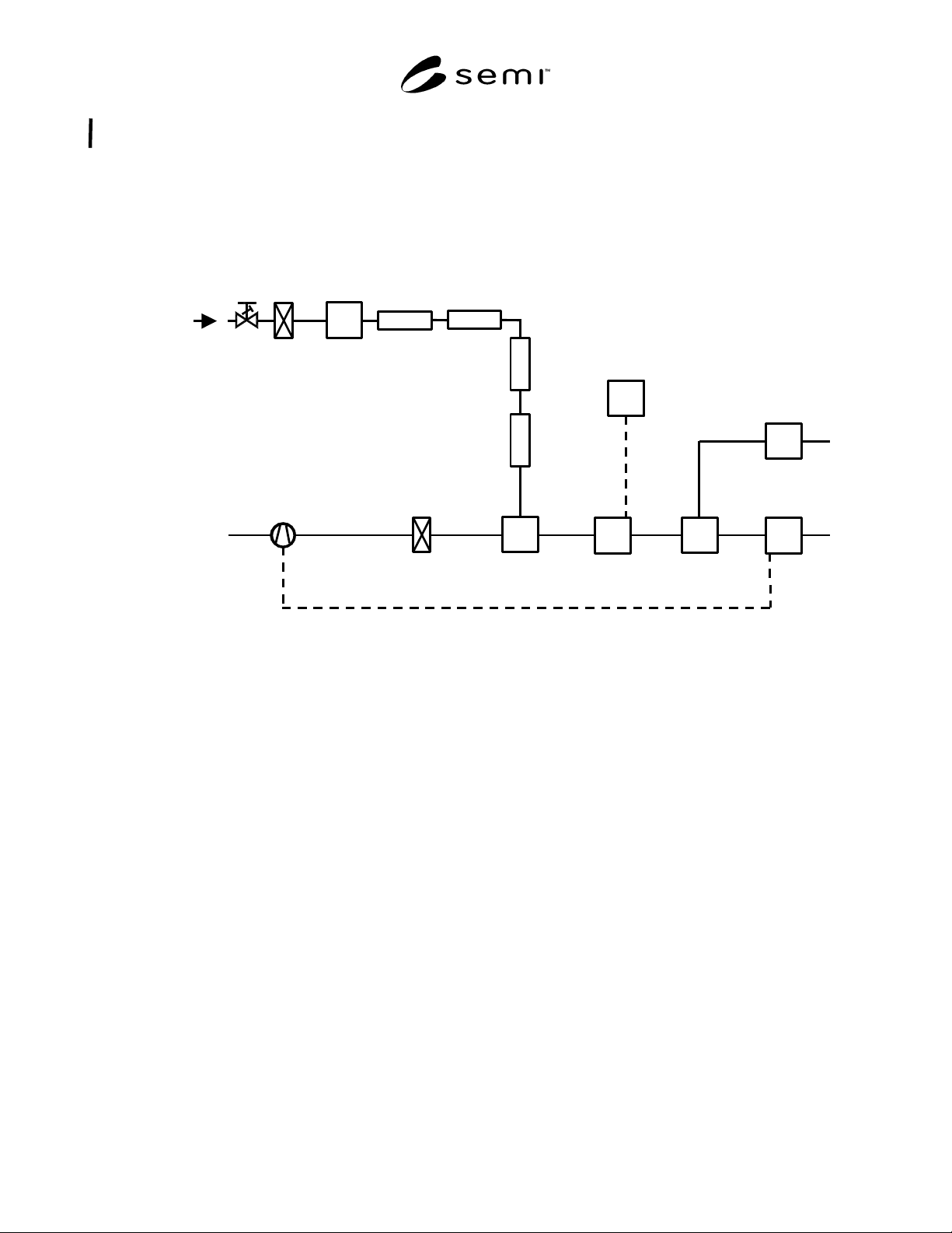
9.2.2.8.3 Figure 1 illustrates a recommended
calibration aerosol generation system.
9.2.2.9 Flow Control
9.2.2.9.1 The velocity of aerosol and the zero gas
should be within the stipulated range v
L, min
... v
L,max
,
specified by the manufacturer of the LPPD. Dependent
on the line diameter D
L
, a stipulated aerosol flow is
necessary. The velocity meter (e.g. thermoanemometer)
or flow meter should be mounted in a line with known
diameter D
VM
.
NOTE 8: The aerosol drawn by the reference particle counter
influences the velocity or flow measured by the velocity
meter or flow meter if it is mounted behind the probe inlet.
This is taken into account when calculating and adjusting the
flow and velocity v
L
at the LPPD. If the velocity meter or
flow meter is mounted in front of the probe inlet of the
reference particle counter, the device should have no
influence on the particle size distribution measured by the
reference particle counter.
9.2.2.10 Calibration Line System
9.2.2.10.1 The system consisting of
• a device to inject the particles into the zero gas,
• a device to mix the aerosol sample with the zero
gas to obtain uniform particle concentration,
• a device to adapt the LPPD into the line (diameter
D
L
),
• a device to adapt the velocity meter or the flow
meter,
• a device (diameter D
RC
= D
L
, same particle
concentration as at the LPPD) to draw a defined,
isokinetic sample from the line for the reference
particle counter (the opening area of the probe inlet
should be reported in the calibration report form),
and
• tubing connecting the devices with each other and
with the fan and filter system.
9.2.2.10.2 The line system should be smooth, conduc-
tive, and electrically grounded to minimize electrostatic
interaction of the particles with line walls and the parti-
cles themselves. The line should be as short and straight
as possible with no bends with a radius of curvature less
than 100 mm. Leak-free connections of the line and all
devices should be ensured using appropriate fittings.
9.2.2.10.3 Figure 1 illustrates a recommended LPPD
calibration system.
NOTE 9: The distance between the device to adapt the LPPD
under test and the device for sample acquisition for the
reference particle counter should be as short as possible to
minimize particle loss and to ensure comparable particle
concentrations.
9.2.2.11 Reference Particle Counter (RPC)
9.2.2.11.1 The reference particle counter is required to
measure the actual concentration of the monodisperse
aerosol and the quality of the zero gas inside the line.
Therefore, the counting efficiency of the reference
particle counter is defined as 100% over the range of
particle sizes used in the test. The resolution should be
better than 10% at the lower detection limit of the
LPPD under test. The values of the measurement
should be printed out in counts per mm
2
opening area
A
RC
of the probe inlet. The sample transit line from the
probe inlet and the reference particle counter should be
as short and as straight as possible. Smooth, conductive,
and electrically grounded materials should be used.
9.2.2.12 Sensor Window Temperature
9.2.2.12.1 Some LPPDs have the capability to heat
their sensor windows to avoid coating of the window. A
device to measure and to adjust the sensor window
temperature within the operating range (measurable to
5%) should be installed in the calibration setup. The
thermometer should be calibrated with an accuracy of
0.2° C.
9.2.2.13 Pulse Height Analyzer (PHA)
9.2.2.13.1 The external analyzer is connected with the
analog sensor calibration output. The PHA should have
at least 64 channels and a resolution of at least 1% of
the average voltage that will be measured. The use of a
PHA, which is built into the sensor electronics, is
allowed if this PHA meets the criteria mentioned above.
The required range and speed will depend on the
performance of the LPPD under test. These parameters
should be obtained by the LPPD manufacturer.
9.2.2.14 Environmental Monitoring
9.2.2.14.1 The environmental temperature T
A
is
measured by a thermometer calibrated with an accuracy
of 0.2° C.
9.2.2.14.2 The environmental relative humidity RH is
measured by a hygrometer.
9.2.2.14.3 The atmospheric pressure p is measured by a
barometer calibrated with an accuracy of 133 Pa.
SEMI E104-0303 © SEMI 2000, 2003 9
9.2.2.15 All instruments used for the reference calibration procedure shall have been checked for valid calibration
in accordance with ISO 10012-1 and 10012-2. Record all calibration data.
9.2.3 Setup and Schematic
9.2.3.1 See Figure 1.
Neutralizer
Dryer
Aerosol
Generator
ULPA
Filter
Compressed,
Dried Air
Dilution
Aerosol Size
Separator
PHA
Fan
ULPA
Filter
LPPD
Analog Output
Reference
Particle
Counter
Injection and
Mixing Device
V´
L
, C
L
,
D
L
, v
L
D
VM
, v
VM
V´
G
C
G
V´
0
Velocity or Flow
Meter and Control
D
RC
Sample
Acquisition
Device
Figure 1
Calibration setup and schematic
9.3 Calibration Procedure
NOTE 10: Specific procedures for calibrating different
LPPDs can vary considerably not only between manufacturers
but between instrument models. For this reason, this
document cannot provide detailed procedures for calibrating
every LPPD. For detailed procedures for calibrating a specific
LPPD, contact the manufacturer. The calibration should be
performed by a skilled technician.
9.3.1 If the aerosol flow rate is varied, then particle
residence time in the detection area A
L
will also vary.
This results in pulses of varying duration. Therefore,
the particle velocity v
L
at the LPPD should be constant
and independent of the line diameter D
L
. The fan has to
be regulated so that the aerosol velocity at the velocity
meter is v
VM
= v
L
D
2
L
/ D
2
VM
. At a constant volume
flow rate V´
G
(depending on the pressure of the
compressed air) and constant number concentration C
G
the level of number concentration C
L
reaches a value
dependent on line diameter D
L
at constant velocity v
L
.
With the known detection area A
L
of the LPPD, the
number of particles per time (counts per mm
2
detection
area per time) is defined. The RPC monitors the number
of particles C
L
of the aerosol generator and the zero air
inside the line.
9.3.2 If the response signal for the used particle size
does not meet the expectations, the operator might use
another particle size within the required size range.
9.3.3 Calibration Parameters
9.3.3.1 The sample measurement time for the
calibration with each particle size should be at least 30
seconds to avoid statistical errors.
9.3.3.2 The calibration is to be performed at ambient
atmospheric pressure in a controlled environment
(temperature, humidity, vibrations).
9.3.3.3 The calibration of the LPPD is to be executed
in a line diameter D
L
in which the LPPD should be
installed by the user.
9.3.3.4 Fixed particle concentration at the LPPD C
P
to
ensure that the coincidence error is always less than
10%.

SEMI E104-0303 © SEMI 2000, 2003 10
9.3.3.5 Fixed velocity at the LPPD: v
L
= 1 m/s
(independent of line diameter at the LPPD).
9.3.3.5.1 Some LPPDs, e.g. a scanning LPPD for the
use inside a process chamber, require a different
velocity than 1 m/s for calibration. In such cases the
used aerosol velocity at the location of the LPPD shall
be reported in the calibration report form.
9.3.4 Initial Setup
9.3.4.1 Connect the aerosol generator to a supply of
filtered, dried, and compressed zero gas (see Figure 1).
Connect a dryer, neutralizer, and size separator (if
necessary) to the aerosol outlet of the particle generator.
If a dilution of the aerosol before the injection in the
calibration line is necessary, install a dilution stage
behind the size separator.
9.3.4.2 Connect the aerosol line to the calibration line.
Mount the LPPD under test behind the injection and
mixing device. Install the sample acquisition device and
the velocity or flow meter into the calibration line.
9.3.4.3 Connect a PHA to the sensor calibration output
if an appropriate built-in PHA is not available.
9.3.4.4 Before starting the following procedures, make
sure all instruments are turned on and allow a certain
time for warm-up and temperature stabilization.
9.3.4.5 Purge the aerosol line and the calibration line
with filtered and dried air for a minimum of 30 minutes.
9.3.4.6 Check the quality of the zero gas and the
condition of the calibration line using the RPC. Collect
counts for three one-minute periods and determine the
average number of particles reported in counts per
minute. The volume flow of the zero gas shall be
enough for correct operation of the RPC. Record the
cumulative particle count reported for the zero gas for
particles equal to and larger than the LDL of the LPPD
under test.
9.3.4.7 Clean the aerosol generator liquid reservoir and
fill it with clean diluent (particle-free deionized or
destilled water or Isopropanol). Run the aerosol
generator and adjust the pressure and flow rates as
recommended by the aerosol generator manufacturer.
Check the condition of the aerosol line using the RPC.
Collect counts for three one-minute periods and
determine the average number of particles reported per
liter of air. If the number exceeds 1 particle per liter air,
the diluent shall be refiltered before further use. The
average number of particles (counts per minute) should
be reported in the calibration report form.
9.3.4.8 Adjust the volume flow through the calibration
line for the stipulated aerosol velocity at the LPPD
under test.
9.3.4.9 Allow a certain time for stabilization of the
adjusted calibration parameters before any test is
performed.
9.3.5 Sizing LPPD
NOTE 11: For more information and background see
Appendix 2.
9.3.5.1 Size Calibration
NOTE 12: To define the calibration settings either the mode
or median of the voltage pulse distribution could be used. The
use of the modal procedure is common. The calibration report
form should identify the used method.
9.3.5.1.1 By running different monodisperse aerosols
(with v
L
and V´
L
= V´
0
+ V´
G
), size calibration is
performed. Begin with the largest particles for which a
calibration value is required. Select the particle size
range for which calibration is required. Be sure that the
particle concentration is low enough that predominantly
individual pulses are generated by the LPPD.
Accumulate enough data to avoid statistical errors. The
procedure is repeated for each particle size of interest.
Determine the average LPPD pulse voltage amplitude
with the PHA.
9.3.5.1.2 The mode of the voltage pulse distribution is
determined by the highest point in the distribution. If
the distribution is interfered with noise near the peak
and the peak is not well defined, the data should be
averaged and the peak of the averaged distribution
should be used defining the mode.
9.3.5.1.3 The median voltage is determined by defining
a “Region of Interest” (ROI) which includes the peak
representing the voltage pulses from single polymer
spheres. The PHA determines the total number of
pulses under this peak. The median voltage is that
voltage which devises the number of pulses in the
region such that half are greater and half are less than
the median.
NOTE 13: If the procedure is carried out for the smallest size
of which the LPPD is specified, record the noise level of the
LPPD. The average voltage for this size should be at least
10% higher than stated noise level voltage at which one noise
pulse occurs in one minute.
9.3.5.1.4 The particle size and the average voltage
should be reported in the calibration report form.
9.3.5.1.5 For calibration checks, a reference particle
counter (RPC) with a good sizing capability could be
used. The counting efficiency of the RPC is defined as
100% for the particle sizes used in test. The counts of
the RPC and the LPPD under test in the corresponding
channel should be normalized to a standard detection
area (mm
2
). The ratio of these counts (in %), the
employed particle size and the threshold settings should
be recorded in the calibration report form.