semi合集-English.pdf - 第6414页
SEMI G75.2-069 8 © SEMI 1998 1 SEMI G75.2-0698 TEST METHOD FOR MEA S UREMENT OF ADHESIVE STRENGTH OF LEADFRAME TAPE 1 Summary of Method 1.1 Tw o m et hods are des cribed: 1.1.1 Pull-Up Method — Using a ho o k a ttached t…

SEMI G75.1-0698 © SEMI 19983
8.3.5.1 The concentration of ionic species in the
leadframe tape is given by:
A=
(B − C) × 50
5
where :
A is the ionic content of the leadframe
tape (ppm)
B is the ionic content on the extracted
solution, determined from the calibration
curves (ppm)
C is the ionic concentration of the back -
ground sample (ppm)
8.4 pH Measurements
8.4.1 Place the pH electrode into the sample solution
and record the pH after one (1) minute.
8.5 Electrical Conductivity Measu rements
8.5.1 Place the conductivity cell into the sample
solution and record the conductivity after one (1)
minute.
9 Related Documents
NOTE: Additional information relating to test methods for
these ionic species may be found in the following
specifications:
9.1 SEMI Standard
SEMI G12 — Recommended Practice for Aqueous
Extraction of Ionic Species from Plastics Used to
Package Electronic Devices
9.2 ASTM Specifications
ASTM D 512 — Standard Test Methods for Chloride
Ion in Water
ASTM D 1293 — Standard Test Methods for pH of
Water
9.3 JIS Specification
JIS K 0102 — Testing Methods for Industrial
Wastewater
NOTICE: These standards do not purport to address
safety issues, if any, associated with their use. It is the
responsibility of the user of these standards to establish
appropriate safety and health practices and determine
the applicability of regulatory limitations prior to use.
SEMI makes no warranties or representations as to the
suitability of the standards set forth herein for any
particular application. The determination of the
suitability of the standard is solely the responsibility of
the user. Users are cautioned to refer to manufacturer’s
instructions, product labels, product data sheets, and
other relevant literature respecting any materials
mentioned herein. These standards are subject to
change without notice.
The user’s attention is called to the possibility that
compliance with this standard may require use of
copyrighted material or of an invention covered by
patent rights. By publication of this standard, SEMI
takes no position respecting the validity of any patent
rights or copyrights asserted in connection with any
item mentioned in this standard. Users of this standard
are expressly advised that determination of any such
patent rights or copyrights, and the risk of infringement
of such rights, are entirely their own responsibility.
Copyright by SEMI® (Semiconductor Equipment and Materials
International), 3081 Zanker Road, San Jose, CA 95134. Reproduction o
f
the contents in whole or in part is forbidden without express written
consent of SEMI.
SEMI G75.2-0698 © SEMI 19981
SEMI G75.2-0698
TEST METHOD FOR MEASUREMENT OF ADHESIVE STRENGTH OF
LEADFRAME TAPE
1 Summary of Method
1.1 Two methods are described:
1.1.1 Pull-Up Method — Using a hook attached to a
tensile tester, the tape is pulled away from the
leadframe inner leads.
1.1.2 Push-Down Method — Using a probe attached to
a tensile tester, a leadframe inner lead is pushed away
from the tape.
1.2 The adhesive strength between the lead and the
tape should be measured at 23°C ± 5°C and 250°C.
2 Equipment
2.1 Tensile tester with appropriate load cell, clamping
chucks, and a chart recorder. Tensile tester shall keep
constant the traveling speed of clamping chucks, of
which the traveling distance can be read to the nearest 1
mm, and shall simultaneously record the load imposed
on the sample. It shall measure and record the imposed
load with ± 1% on a chart recorder.
2.2 Pull-Up Method
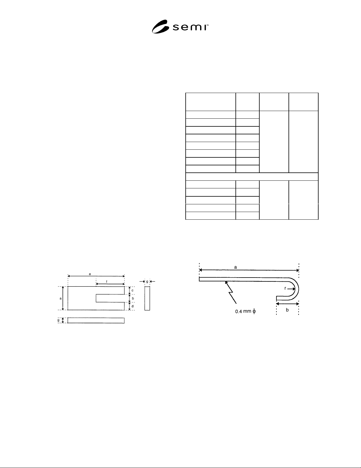
2.2.1 A clamp should be suitable for each leadframe
type. Example of the clamp design, for a typical 40 pins
DIP leadframe, is shown in Figure 1.
Figure 1
Example of Clamp Design
(40 Pins DIP Leadframe)
Table 1 Dimension and Material of Clamp and Hook
in Push-Up Method
Item/Dimension Value Material
Reference
Figure
Clamp
a 60 mm
b8 mm
c 26 mm
d 26 mm
e 60 mm
f 30 mm
g3 mm
Aluminum 1
Pull-Up Hook
φ
0.4 mm
a 100 mm
b5 mm
r 2.0 mm
Piano Wire 2
2.2.2 A pull-up hook should be suitable for each
leadframe type. Example of the pull-up hook, for a
typical 40 pins DIP leadframe, is shown in Figure 2.
Figure 2
Pull-Up Hook
(40 Pins DIP Leadframe)
2.3 Push-Down Method
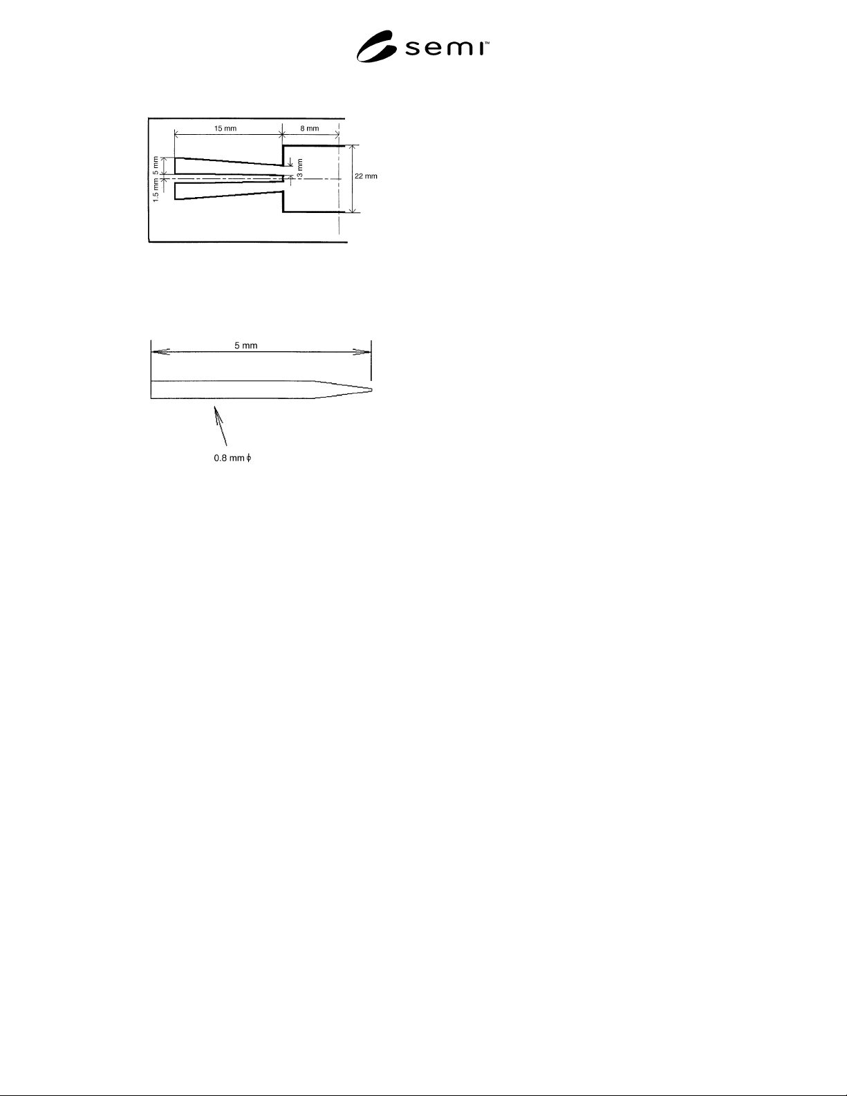
2.3.1 A table should be suitable for each leadframe
type. Example of the table, for a typical 40 pins DIP
leadframe, is shown in Figure 3.
2.3.2 A push-down probe should be suitable for each
leadframe. Example of the push-down probe, for a
typical 40 pins DIP leadframe, is shown in Figure 4.
SEMI G75.2-0698 © SEMI 1998 2
Figure 3
The Dimension of the Table
Figure 4
Example of Push-Down Probe
(40 Pin DIP Leadframe)
3 Test Condition
3.1 Adhesion testing shall be carried out at the
following ambient conditions:
Temperature — 23°C ± 5°C
Humidity — 50 ± 5% RH
4 Sampling
4.1 The sampling is one sample per one lot. The
vendor must report the definition of lot, if the customer
requires it.
5 Preparation of Specimens
5.1 Leadframe Manufacturers
5.1.1 Leadframes shall be taped using conditions for
temperature, pressure, and dwell-time agreed upon
between vendor and customer.
NOTE: A typical taped 40 pins DIP leadframe is shown in
Figure 5, and relevant information for this frame is shown in
Table 2.