semi合集-English.pdf - 第4121页
SEMI F62-0701 © SEMI 2001 1 SEMI F62-0701 TEST METHOD FOR DETERMINING M A SS FLOW CONTROLLER PERFORMANCE CHARACTERISITI CS FROM AMBIENT AND GAS TEMPER A TURE EFFECTS This spe cification was te chnically approve d by the …
SEMI F61-0301 © SEMI 20015
Feed
Water
≤
≤
≤
≤ 5
µ
µµ
µ
≤
≤≤
≤ 1
µ
µµ
µ
≤
≤
≤
≤ 1
µ
µµ
µ
≤
≤
≤
≤ 0.02
µ
µµ
µ
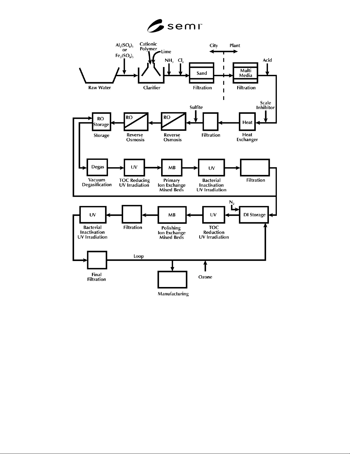
Figure 1
Schematic of a Typical Ultrapure Water System
NOTICE: SEMI makes no warranties or representations as to the suitability of the standards set forth herein for any
particular application. The determination of the suitability of the standard is solely the responsibility of the user.
Users are cautioned to refer to manufacturer’s instructions, product labels, product data sheets, and other relevant
literature respecting any materials or equipment mentioned herein. These standards are subject to change without
notice.
The user’s attention is called to the possibility that compliance with this standard may require use of copyrighted
material or of an invention covered by patent rights. By publication of this standard, SEMI takes no position
respecting the validity of any patent rights or copyrights asserted in connection with any item mentioned in this
standard. Users of this standard are expressly advised that determination of any such patent rights or copyrights, and
the risk of infringement of such rights, are entirely their own responsibility.
Copyright by SEMI® (Semiconductor Equipment and Materials
International), 3081 Zanker Road, San Jose, CA 95134. Reproduction o
f
the contents in whole or in part is forbidden without express written
consent of SEMI.

SEMI F62-0701 © SEMI 20011
SEMI F62-0701
TEST METHOD FOR DETERMINING MASS FLOW CONTROLLER
PERFORMANCE CHARACTERISITICS FROM AMBIENT AND GAS
TEMPERATURE EFFECTS
This specification was technically approved by the Global Facilities Committee and is the direct
responsibility of the North American Facilities Committee. Current edition approved by the North American
Facilities Committee on March 22, 2001. Initially available at www.semi.org May 2001; to be published July
2001.
1 Purpose
1.1 The purpose of this document is to define a
method for testing MFCs being considered for
installation into a gas distribution system and to
quantify ambient and gas temperature effects on the
MFC's indicated and actual flow.
2 Scope
2.1 This test method applies to metal and polymer
sealed MFCs with flow rates up to 30 slpm. The tests
include those listed below and are to be performed in
the following order:
1. Ambient Temperature Effects (Steady State and
Transient)
2. Gas Temperature Effects (Steady State and
Transient)
2.2 This standard does not purport to address safety
issues, if any, associated with its use. It is the
responsibility of the users of this standard to establish
appropriate safety health practices and determine the
applicability or regulatory limitations prior to use.
3 Limitations
3.1 This method evaluates mass flow controllers in
typically encountered, realistic operating conditions.
3.2 This test method does not address operational
influences outside of the manufacturer's published
limitations.
4 Referenced Standards
4.1 None.
5 Terminology
5.1 Acronyms and Abbreviations
5.1.1 DUT — device under test
5.1.2 g — gravity
5.1.3 kPa — kiloPascal
5.1.4 MFC — mass flow controller
5.1.5 NIST — National Institute of Standard Tech-
nologies
5.1.6 sccm — standard cubic centimeters per minute
5.1.7 slpm — standard liters per minute
5.2 Definitions
5.2.1 stability, long term — reading ± 2% for over one
hour.
5.2.2 stability, short term — reading ± 2% within five
minutes.
5.2.3 zero setpoint — manufacturer's setpoint for no
flow from the MFC.
5.3 Descriptions of Terms
5.3.1 MFC
1
— inlet mass flow controller.
5.3.2 T
a
— the temperature in the environmental
control chamber.
5.3.3 T
g
— gas temperature at the inlet to the DUT.
5.3.4 T
max
— maximum manufacturer-rated temper-
ature for an MFC.
5.3.5 T
min
— 20°C or manufacturer rated minimum
temperature, whichever is greater.
5.3.6 TC
g
— temperature coefficient due to changing
gas temperature of DUT.
5.3.7 TC
e
— temperature coefficient due to changing
environmental temperature of DUT.
5.3.8 Q
a
— for the purpose of this method, the output
value of the flow standard in units of mass flow.
5.3.9 Q
ind
— for the purpose of this method, the output
value of the device under test in units of mass flow.
5.3.10 Q
sp
— for the purpose of this method, the
intended output in mass flow units for a particular
setpoint.
5.3.11 V
a
— valve A
5.3.12 V
b
— valve B
5.3.13 V
I i
— inlet isolation valve

SEMI F62-0701 © SEMI 2001 2
5.3.14 V
io
— outlet isolation valve
6 Significance and Use
6.1 This test method defines a procedure for testing
components being considered for installation in a gas
distribution system. Application of this method is
expected to yield data allowing an end user to choose
among components tested for the purpose of
qualification for this installation.
7 Apparatus
7.1 See Figures 1a and 1b for schematics of the set-
ups.
7.2 Flow Measurement Device, National Institute of
Standard Technologies (NIST) traceable and capable of
measuring steady-state and transient flow
characteristics, preferably with differential pressure
sensors across a flow restriction. This device should
have a relative accuracy of at least 2 to 1 with respect to
the DUT.
7.3 Temperature Measurement Device, to measure test
gas temperature, NIST traceable and capable of real-
time measurement, with a low mass (< 0.05 g) sensor
and with low thermal losses through the leads (< 0.3
mW/°C).
7.4 Pressure Measurement Device, to measure test gas
pressure, NIST traceable, and capable of real-time
measurement to measure test gas pressure.
7.5 Gas Pressure Control Regulators, to maintain test
gas pressure at 275 kPa ± 5 kPa.
7.6 Gas Temperature Control, heat exchangers and
heaters to maintain the gas temperature equal to the test
temperature within ± 1 °C at the test flow rates.
7.7 Environmental Chamber, capable of stable
temperature control (± 1°C) from at least T
min
to a point
exceeding the maximum rated MFC temperature by
10°C.
8 Reagents and Materials
8.1 Test Gas, clean, dry nitrogen.
8.2 Tubing, cleaned and maintained to have no adverse
effects on the test.
8.3 Valves, capable of unimpaired operation at 100°C.
9 Safety Precautions
9.1 All manufacturers’ recommendations should be
followed and noted when testing the unit. Any safety
precautions should always be followed.
9.2 This standard does not purport to address all of the
safety problems, if any associated with its use. It is the
responsibility of the user to establish appropriate safety
and health practices and to determine the applicability
of regulatory limitations before using this method.
10 Technical Precautions
10.1 The flow standard may read a non-zero value due
to heating of the gas in the test to determine transient
effects on the zero. These readings should be noted.
11 Preparation of Apparatus
11.1 Setup and Schematic, (see Figure 1a) Ambient
Temperature Effects
11.1.1 Install an ambient temperature sensing device
within 5–10 centimeters horizontally adjacent to the
MFC body. The probe should not be in contact with the
MFC body or the environmental chamber walls.
11.1.2 Position the gas temperature sensor in the
center of the gas stream no more than 10 cm upstream
from the inlet surface of the MFC body.
11.1.3 After installation of the MFC, flow nitrogen at
a 100% setpoint to purge the system for a sufficient
time to remove atmospheric contamination.
11.1.4 If the MFC has a selectable Auto Zero function,
note this on all data presentation documents before
proceeding with the test.
11.1.5 Minimize the length of tubing between the
heater and the device under test to reduce gas
temperature changes.
11.2 Setup and Schematic, (see Figure 1b) Gas
Temperature Effects
11.2.1 Install a base temperature sensing device, T
e
adjacent to the MFC body. The probe should be in
contact with the MFC body.
11.2.2 Install an ambient temperature sensing device
within 5–10 centimeters horizontally adjacent to the
MFC body. The probe should not be in contact with the
MFC body or the environmental chamber walls.
11.2.3 Position the gas temperature sensor in the
center of the gas stream no more than 10 cm upstream
from the inlet surface of the MFC body.
11.2.4 After installation of the MFC, flow nitrogen at
a 100% setpoint to purge the system for a sufficient
time to remove atmospheric contamination.
11.2.5 If the MFC has a selectable Auto Zero function,
note this on all data presentation documents before
proceeding with the test.