semi合集-English.pdf - 第716页
SEMI E99-1104 E © SEMI 2000, 2004 6 8.3 Read/Write Head Attributes 8.3.1 Table 2 define s the attributes for the Read/Write Head. NOTE 2: In the case of an integrated single head, the attributes in Table 2 are regarded a…

SEMI E99-1104
E
© SEMI 2000, 2004 5
7.3 Upstream Controller
7.3.1 The CIDRW provides certain services when requested by the upstream controller. The upstream controller
sends a message requesting the specified service, and the CIDRW sends a message with the response.
7.3.2 This standard assumes that an upstream controller initiates each service message to the CIDRW, and the
CIDRW sends its response to the upstream controller. The upstream controller must watch the response time to
monitor the communication timeout. This standard will define the recommended method for handling exceptions
caused by timeouts.
7.3.3 In addition, some CIDRW may provide asynchronous notification to the upstream controller. Examples of this
include, but are not limited to, the detection of a fault condition resulting in an alarm. Asynchronous notification is
not required for compliance to this standard.
8 Attributes
8.1 An attribute is an item of information about an entity that is maintained and is available by request. There is
certain information concerning the CIDRW that is of potential interest to the upstream controller, including the
manufacturer, the model, and the serial number of the device. This information is considered as attributes of the
CIDRW and is available on request.
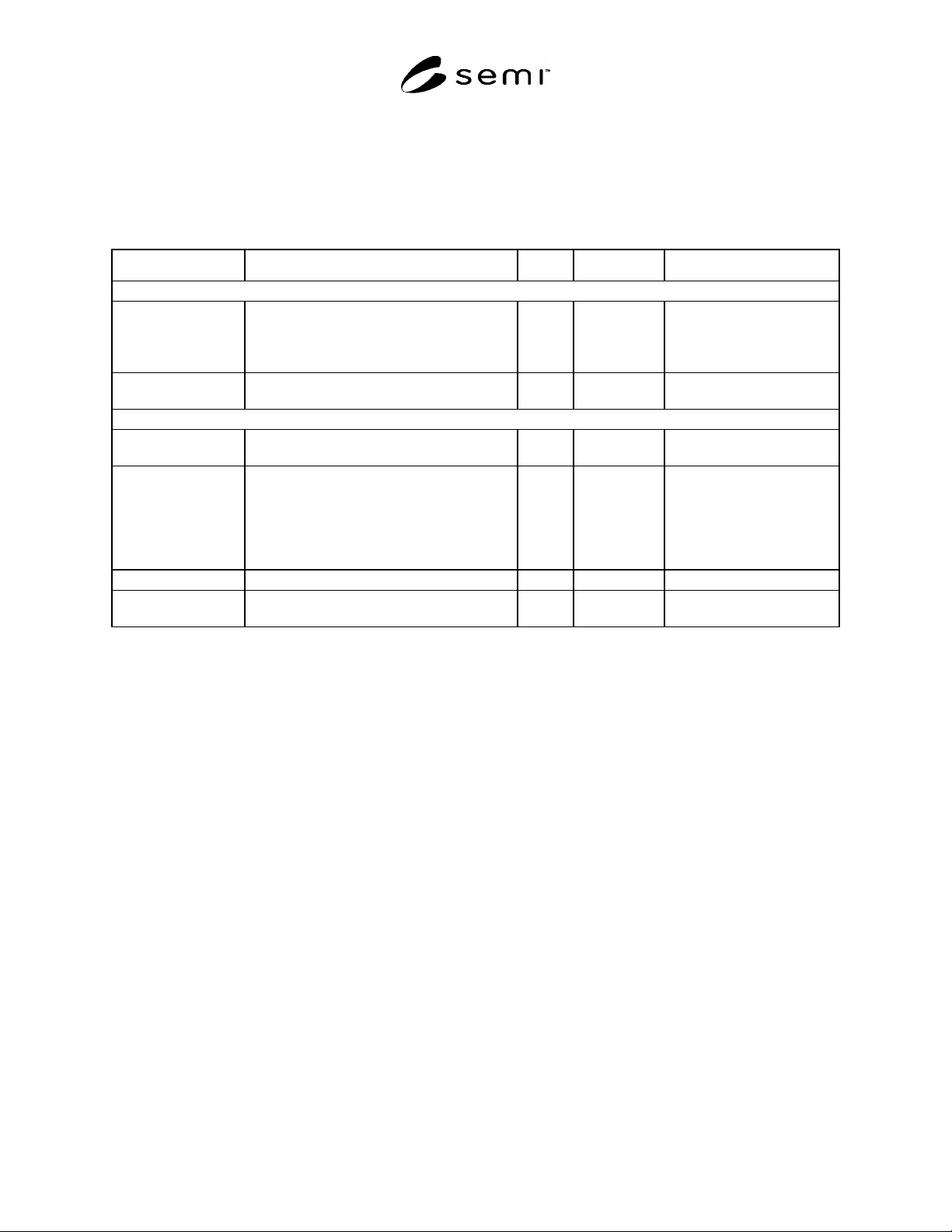
8.2 CIDRW Attribute Definition Table
8.2.1 Table 1 defines the attributes of the Carrier ID Reader/Writer subsystem.
Table 1 CIDRW Attribute Definitions
Attribute Name Description Access Reqd Form
Fundamental
Configuration Number of heads. RO Y Text
Alarm Status Current CIDRW substate of ALARM
STATUS.
RO Y Enumerated:
0 = NO ALARMS
1 = ALARMS
Operational Status Current CIDRW substate of
OPERATIONAL.
RO Y Enumerated:
IDLE
BUSY
MAINTENANCE
SoftwareRevisionLevel Revision (version) of software. RO Y Text
Optional
CarrierIDOffset
Offset position of the first byte for Carrier
ID in the Electric Tag.
RW N 00-15
CarrierIDLength
Length byte of the Carrier ID.
If non-visible ASCII character exists in
this string, CIDRW shall send out an error
to the upstream controller.
RW N 01–16
DateInstalled Date the subsystem was installed. RO N Protocol dependent.
Device Type Identifiers subsystem as either a Carrier ID
Reader or a Carrier ID Reader/Writer.
RO N Text
HardwareRevisionLevel Revision number of the hardware. RO N Text
MaintenanceData Supplier dependent. RO N Text
Manufacturer The name or identifier of the manufacturer. RO N Protocol dependent.
ModelNumber The manufacturers model designation. RO N Text
SerialNumber Subsystem serial number assigned by
manufacturer.
RO N Protocol dependent.
SEMI E99-1104
E
© SEMI 2000, 2004 6
8.3 Read/Write Head Attributes
8.3.1 Table 2 defines the attributes for the Read/Write Head.
NOTE 2: In the case of an integrated single head, the attributes in Table 2 are regarded as an extension of Table 1.
8.3.2 In the case of multiple heads, it must be possible to distinguish between the attributes of different heads.
Table 2 Read/Write Head Attribute Definitions
Attribute Name Description Access Reqd Form
Fundamental
HeadStatus The current state. RO Y Enumerated:
IDLE,
BUSY,
NOT OPERATING
HeadID Head number 0–31 RO Y if
multi-head
Text. 2 digits.
Optional
Cycles Number of read and write operations
performed.
RO N Unsigned integer
HeadCondition The current Maintenance status. RO N Enumerated:
No alarms
Needs Maintenance
Read/Write fault
Read/Write rate fault
No power.
HeadDateInstalled Date this head was installed. RO N Protocol dependent.
HeadMaintenance-
Data
Supplier dependent RO N Text
9 State Models
9.1 To facilitate independent control of the individual heads, this section defines two separate state models, one for
CIDRW subsystem and one to be applied to each of the individual heads.
SEMI E99-1104
E
© SEMI 2000, 2004 7
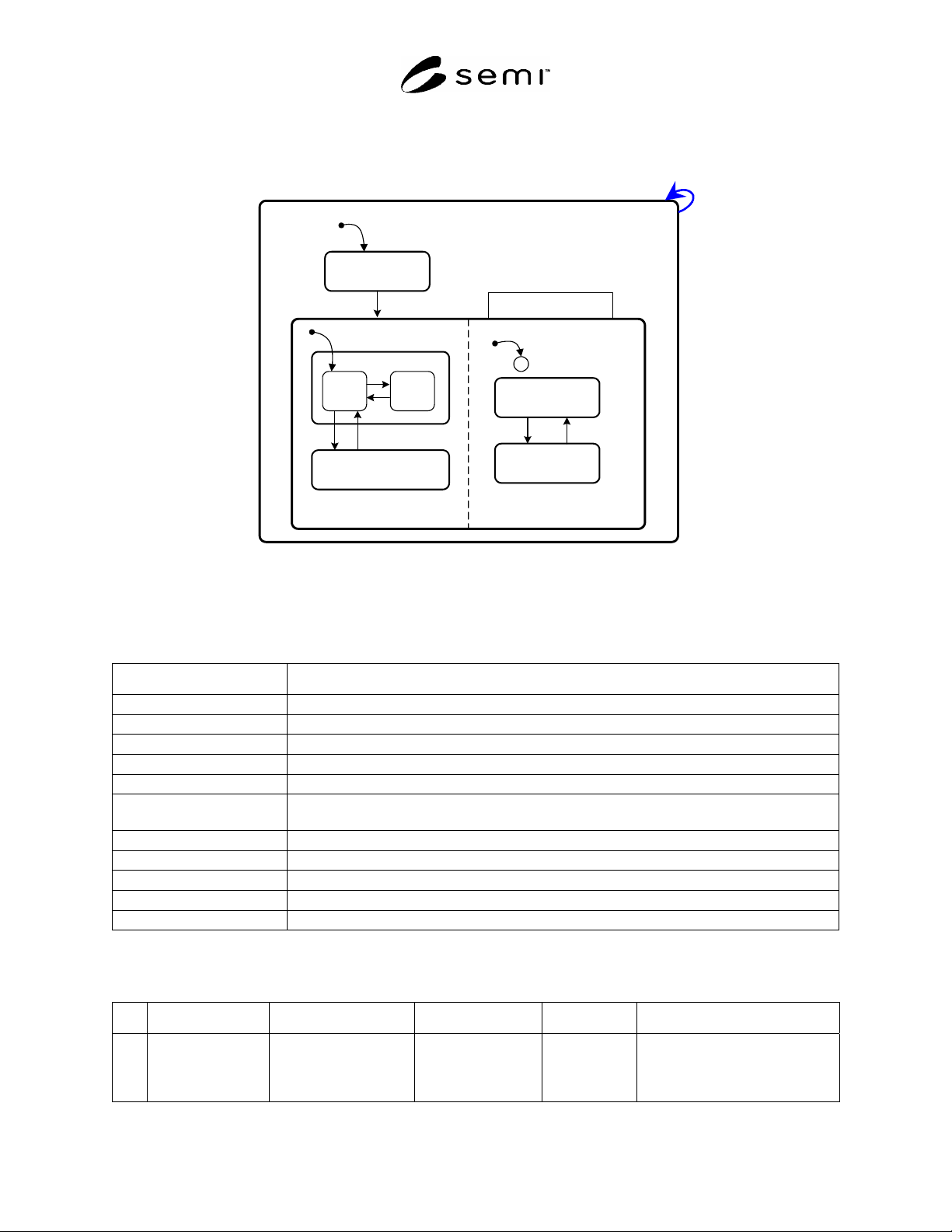
9.2 CIDRW State Model
9.2.1 This section defines the state model for the CIDRW subsystem. Figure 1 shows the diagram for this model.
1
CIDRW
INITIALIZING
OPERATING
3
2
NO ALARMS
ALARMS
C
MAINTENANCE
4
5
910
ALARM STATUSOPERATIONAL STATUS
RUNNING
11
IDLE
7
8
6
BUSY
Figure 1
CIDRW State Model Diagram
9.2.2 Table 3 defines the states of the CIDRW. Definitions are in alphabetical order.
Table 3 CIDRW Subsystem State Definitions
State Definition
ALARM STATUS Shows the presence or absence of alarms.
ALARMS An alarm condition exists.
BUSY A service is being performed that affects the state of the hardware.
CIDRW Superstate of CIDRW State Model. Always active when CIDRW powered on.
IDLE No service is being performed. All heads are idle.
INITIALIZING CIDRW is performing initialization and self diagnostics. Presence or absence of alarms is
initially determined in this state.
NO ALARMS No alarm conditions exist.
OPERATING Normal operational states where reading and/or writing operations can be performed.
OPERATIONAL STATUS The CIDRW is fully capable of performing all services that it supports.
RUNNING The CIDRW is operational and able to communicate.
MAINTENANCE Internal setup and maintenance activities.
9.2.3 Table 4 defines the transitions of the CIDRW State Model.
Table 4 CIDRW State Transitions
# Previous State Trigger New State Actions Comments
1 (Any) Powerup or reset INITIALIZING Initialize
hardware
and software
components.
Default entry on powerup.