semi合集-English.pdf - 第7762页
SEMI T12-0305 © SEMI 2004, 2005 41 RELATED INFORMATION 1 USE CASE OF TRACKING JIGS AND IMPLEMENTS NOTICE: This related information is not an official part of SEMI T12 and was derived fro m the work of the originating tas…
SEMI T12-0305 © SEMI 2004, 2005 40
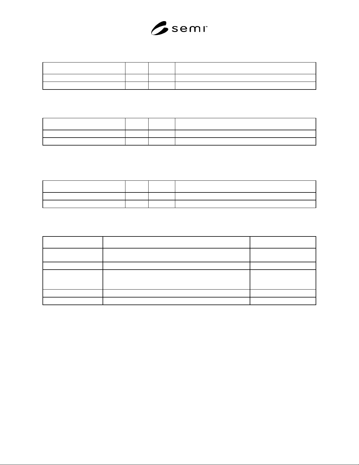
10.2.11.5 showType — This service is used to inquire type of Secondment. Following table defines its parameters.
Table 104
Parameter Req/Ind Rsp/Conf Description
AttachmentType - M Type of Secondment.
ServiceStatus - M Result of service request.
10.2.11.6 showState — This service is used to inquire state of Secondment. Following table defines its parameters.
Table 105
Parameter Req/Ind Rsp/Conf Description
State - M State of Secondment.
ServiceStatus - M Result of service request.
10.2.11.7 destruct — This service is used to remove Secondment object. This service is typically used when an
attachment is removed from equipment. Following table defines its parameters.
Table 106
Parameter Req/Ind Rsp/Conf Description
State - M Immediate state just before removed.
ServiceStatus - M Result of service request.
10.2.11.8 Parameter List — Above services use following parameters.
Table 107
Parameter Definition Form
AttachmentId Identification of Attachment: usually equivalent to physical ID
maybe tagged on physical attachment.
Text.
AttachmentName Human friendly name assigned on an Attachment. Text.
AttachmentType Type of Attachment: at least jig or implement, and based on
attachments’ compatibility. Further classification is dependent on
manufacturer, attachment, equipment or strategy of its user.
Enumerated.
ServiceStatus Result of service to show successful or reason of failure. Text.
State Occupancy state of PublicLocation object. Text.
SEMI T12-0305 © SEMI 2004, 2005 41
RELATED INFORMATION 1
USE CASE OF TRACKING JIGS AND IMPLEMENTS
NOTICE: This related information is not an official part of SEMI T12 and was derived from the work of the
originating task force. This related information was approved for publication by full letter ballot procedures on
January 9, 2004.
R1-1 Use Case Diagram
R1-1.1 Use Case diagram is one of good start point to understand and analyze problem domain. It is often used
before modeling a system.
R1-1.2 Use Case diagram consists of Actors and Use Cases. A use case defines something expected to a system
related to an actor or between actors. All use cases build up whole system.
R1-2 Use Case Diagram of Attachment Tracking
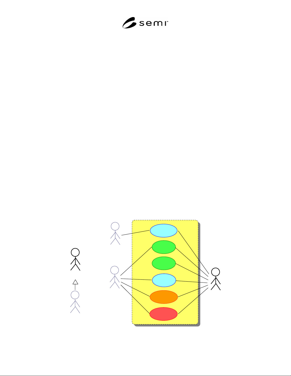
R1-2.1 Figure R1-1 is for use cases of Jigs and Implements.
R1-2.2 Update Inventory — Jig Handler updates when it takes jig to or brings from equipment. Tool updates when
jig has arrived (and verified) and removed.
R1-2.3 Update or Check History — Tool reports when it uses some amount of cycle or such things as maintenance,
inspection or problem happens. Superintendent checks history of a jig. Provided information is based on data in
database with inquiry about current delta on equipment.
R1-2.4 Manage Exception — Tool reports when some exception happens. Superintendent instructs something.
Tool replies.
R1-2.5 Invoice — Superintendent send invoice to let tool know which jig is delivered. Tool asks whether received
jig is right one or not. If something is wrong, an exception process is required.
R1-2.6 Manage Expiration — When Jig is used repeatedly and it use-time or cycles reaches preset value, tool has to
make some expected action to avoid unexpected processing.
R1-2.7 Manage Exception — Superintendent configures effective period or cycle of a Jig. Tool stop using the Jig
or notify the event when it is expired.
Update
History
Superinten
dent
Too l
(
Ji
g
User
)
Check
History
Invoice
Manage
Expiration
Update
Inventory
Jig
Handler
Superinten
dent
Too l
(
Ji
g
User
)
Manage
Exception
Figure R1-1
SEMI T12-0305 © SEMI 2004, 2005 42
RELATED INFORMATION 2
AN EXAMPLE ON EQUIPMENT WITH SECS-II AND GEM
NOTICE: This related information is not an official part of SEMI T12 and was derived from the work of the
originating task force. This related information was approved for publication by full letter ballot procedures on
January 9, 2004.
R2-1 GEM Level Example
R2-1.1 This example is a possible implementation of attachment tracking capabilities “Acquisition of Minimum
Tracking Information” and “Action on Expiration” with SEMI E5 (SECS-II) and SEMI E30 (GEM).
R2-1.2 Great many equipment and production lines adopt GEM level implementation around the world because it
was standardized more than ten years ago and was the only unified communication standard between equipment and
factory host computer for long period.
R2-2 Example Scenario
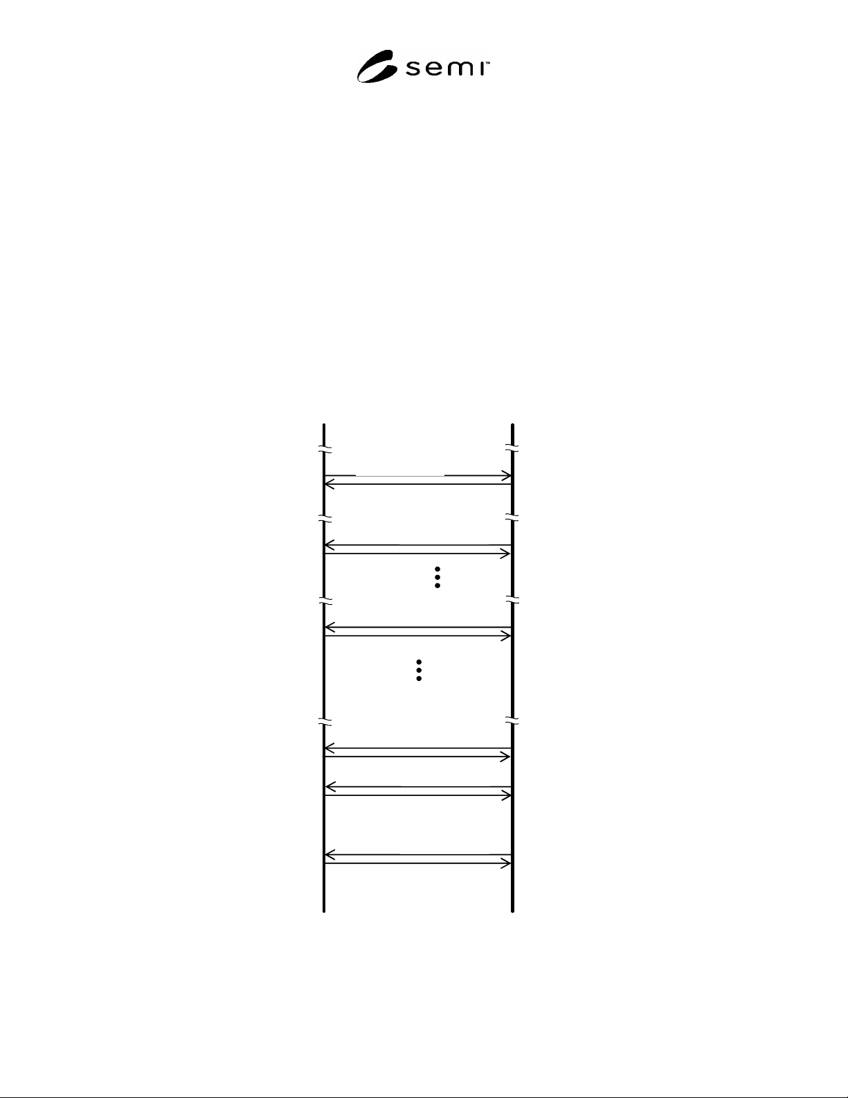
R2-2.1 An example scenario consists of setting up expiry, tracing data of an attachment and hitting expiration.
Host
Equipment
S2F15 (ECS)
or S2F41 (HCS)
S2F16 (ECA)
or S2F42
(
HCA
)
Settin
g
Ex
p
iration
A
cknowled
g
e
S6F11
(
ERS
)
S6F12
(
ERA
)
Acknowled
g
e
C
y
cle Increment
S6F11
(
ERS
)
S6F12
(
ERA
)
Acknowled
g
e
Use-Time Increment
S6F11
(
ERS
)
S6F12
(
ERA
)
Acknowled
g
e
Expired and
Equipment Stops
S5F1
(
ARS
)
S5F2
(
ARA
)
Acknowled
g
e
A
larm Raised
S5F1
(
ARS
)
S5F2
(
ARA
)
Acknowled
g
e
A
larm Cleared
Figure R2-1