semi合集-English.pdf - 第6464页
SEMI G77-0699 © SE MI 1999 5 bilateral datum plane y 1 =193 ± 0.25 x 1 ≤ 203.5 x 2 ≤ 240 (at hu man handle) bottom rail x 56 = 194.75 ± 0.25 x 57 ≤ 187 facial datum plane x 13 = 88.5 x 14 = 118.5 y 18 = 40.2 y 19 = 61.1 …
SEMI G77-0699 © SEMI 1999 4
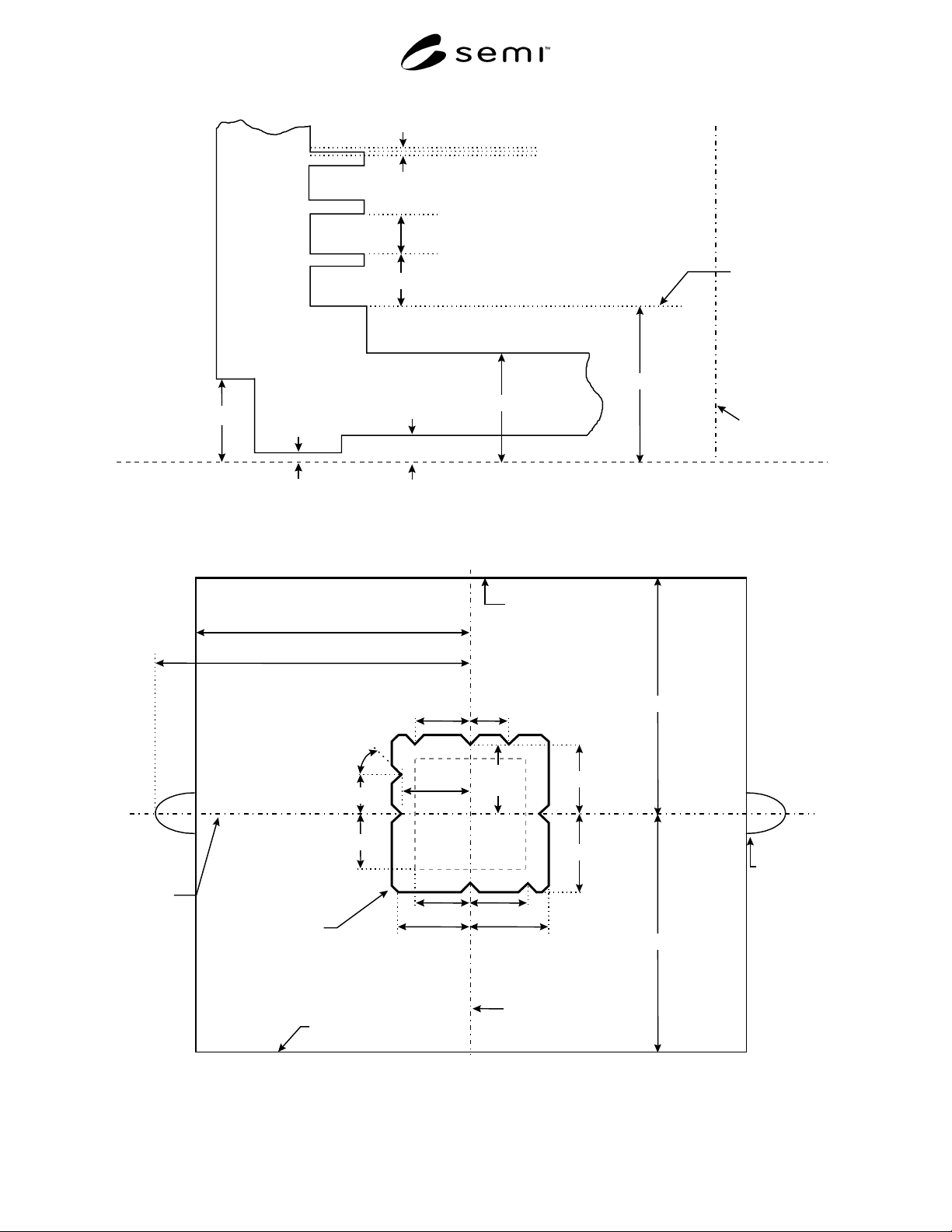
horizontal
datum plane
bilateral
datum plane
z
4 = 33
bottom nominal
tape frame
seating plane
z
5 = 10
z
12 = 0
±
0.5
(height of tape frame bottom)
z
6
≥
5
z
3
≤
23
z
8
≥
15
z
43 = 1
+
0
−
1
z
41
≥
1
Figure 3
Detail of Film Frame Supports
bilateral
datum plane
facial
datum
plane
y
1 = 193
±
0.25
x
1
≤
203.5
x
2
≤
240 (at human handle)
human
handle
(optional)
x
41 = 30
± 1
x
42 = 50
±
1
y47
≥
58
y
46 = 71
±
1
y
45
= 65.3
±
1
x
45
= 65.3
±
1
x
43 = 50
±
1
x
44
≤
53
x
46 = 71
±
1
x
47
≥
58
y
44
≤
53
y
41 = 30
±
1
(16x)
θ = 45
±
0.5
°
y5
≤
200
front side where tape
frames are accessed
top flange
(optional)
rear cover
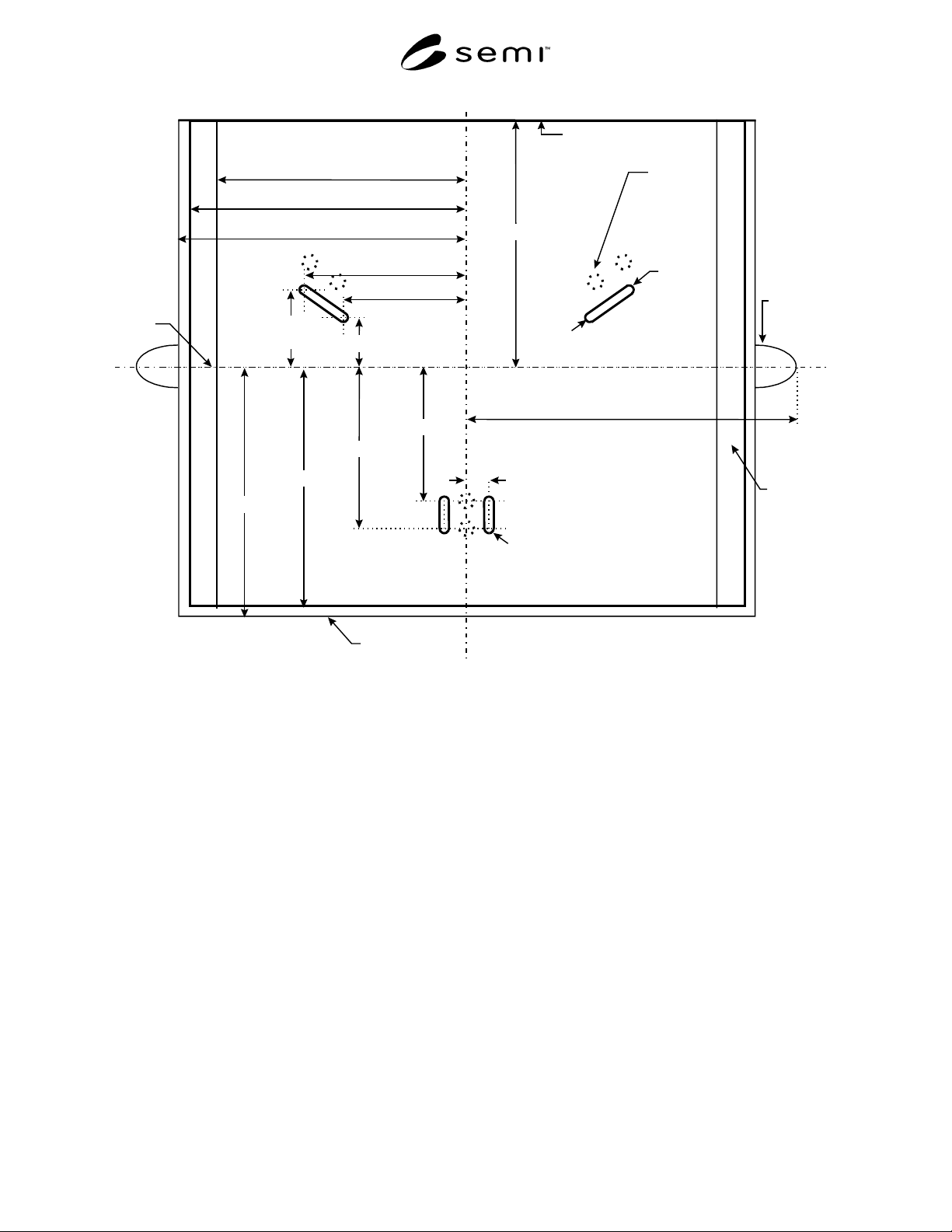
Figure 4
Top View of Frame Cassette
SEMI G77-0699 © SEMI 19995
bilateral
datum plane
y
1 =193
±
0.25
x
1
≤
203.5
x
2
≤
240 (at human handle)
bottom
rail
x
56 = 194.75
±
0.25
x
57
≤
187
facial
datum
plane
x
13 = 88.5
x
14 = 118.5
y
18 = 40.2
y
19
= 61.1
r13
≥
2.5
r
13
≥
2.5
y
9 = 92.5
y
10 = 123.5
x
17 = 17.5
kinematic
coupling
pins
carrier
sensing
pads
human
handle
(optional)
front side where tape
frames are accessed
rear cover
y
5
≤
200
y
2 = 193
±
0.25
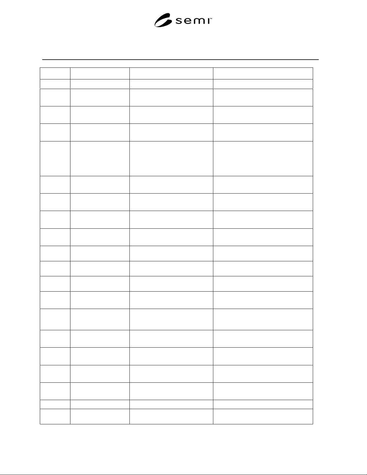
Figure 5
Bottom View of Frame Cassette
SEMI G77-0699 © SEMI 1999 6
Table 1 Dimensions for Frame Cassette
Symbol Value Specified Datum Measured From Feature Measured To
θ‡
45 ± 0.5° either vertical datum plane sides of position and orientation notches
r13† 2.5 mm
2.6 minimum
line segment along center of
cassette sensing pad
edge of cassette sensing pad
x1 203.5 mm
maximum
bilateral datum plane outer surface of frame cassette (without
handles)
x2 240 mm
maximum
bilateral datum plane furthest reach of human handles
x3 177 mm
minimum
187 mm
maximum
bilateral datum plane inside edge of tape frame support
x4 191.5 ± 0.3 mm bilateral datum plane inside wall of frame cassette
x13† 88.5 mm bilateral datum plane
near end of line segment along center of
front cassette sensing pads
x14† 118.5 mm bilateral datum plane far end of line segment along center of
front cassette sensing pads
x17† 17.5 mm bilateral datum plane line segment along center of rear cassette
sensing pads
x41‡ 30 ± 1 mm bilateral datum plane front right orientation notch on robotic
handling flange
x42‡ 50 ± 1 mm bilateral datum plane front left orientation notch on robotic
handling flange
x43‡ 50 ± 1 mm bilateral datum plane rear orientation notch on robotic handling
flange
x44‡ 53 mm
maximum
bilateral datum plane encroachment of box underneath robotic
handling flange
x45‡ 65.3 ± 1 mm bilateral datum plane
nearest point of side position and
orientation notches on robotic handling
flange
x46‡ 71 ± 1 mm bilateral datum plane sides of robotic handling flange
x47‡ 58 mm
minimum
bilateral datum plane end of robotic handling flange front and
rear
x56‡ 194.75 ± 0.25 mm bilateral datum plane outside edge of bottom rails
x57 187 mm
maximum
bilateral datum plane box sides underneath bottom rails
y1 193 ± 0.25 mm facial datum plane front outside edge of frame cassette
y2 193 ± 0.25 mm facial datum plane back outside bottom edge of frame
cassette