semi合集-English.pdf - 第1472页
SEMI 30.1-0200 © SEMI 1998, 2000 47 6. L, 2 1. L, 2 1. <ATTRID= “Process ProgramID”> 2. <AT TR DAT A= “M y R ec ip e”> 2. L, 2 1. <ATTRID= “ProcessL e vel”> 2. <ATT RDAT A= “My Le ve l”> 7. L, c 1…
SEMI 30.1-0200 © SEMI 1998, 2000 46
RELATED INFORMATION 2
APPLICATION NOTES
NOTE: The material contained in these Application Notes is not an official part of SEMI E30.1 and is not intended to modify or
supersede the official standard. Rather, these notes describe possible methods for implementing certain ISEM requirements
described by the standard and are included as reference material.
R2-1 Using ISEM Table Attributes to Specify Process Related Data Item Variable Values
R2-1.1 Section 11.1 (ISEM Table Data) allows the host to use ISEM Table attributes to specify product and process
related information related to the table data. The ISEM Variable Item Dictionary (Table 4) includes seven data items
intended to be used for this purpose. They are identified with the comment “This information may be added by the
host in the ISEM Tables.” Identifying the value of variable data items in Table attributes is not covered in use of
ISEM Tables. One method to accomplish this is to use attribute identifiers (ATTRIDn) that are the same identifiers
that are used for the equipment variable data items (Table R2-1). (This is very similar to the method specified in
Section 12.5 to identify values to override the default values of variable process program parameters using the “PP-
SELECT” remote commands).
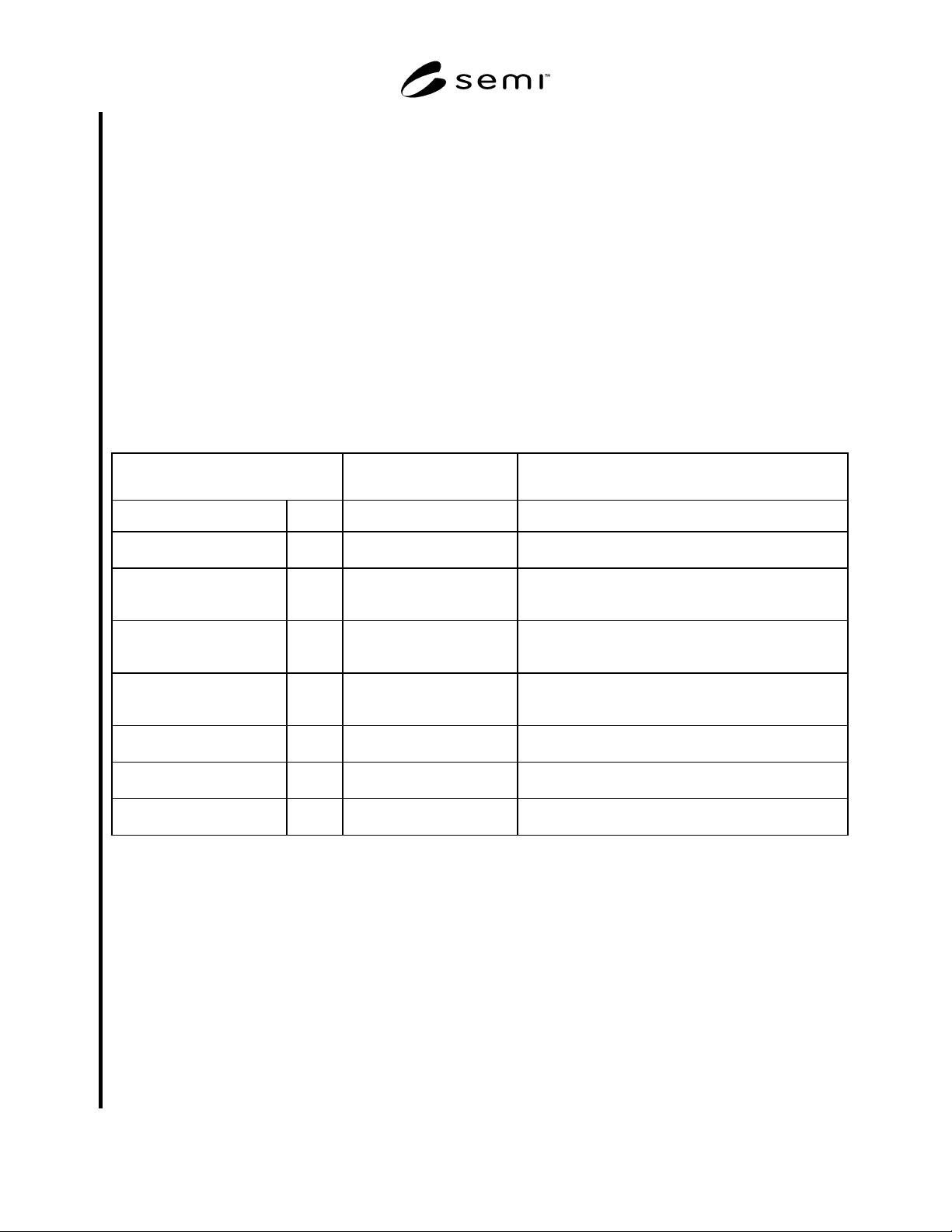
Table R2-1 ISEM Variable Items and Their Equivalent ISEM Table Attribute Identifiers
Variable Item
(Table 4)
ISEM Table Attribute
Identifier
Description
Name Type
OperatorID DV OperatorID Identification of the operator of the inspection/review
equipment.
ProcessEquipmentID DV ProcessEquipmentID Identification of the process equipment used with the
current material immediately prior to the
inspection/review.
ProcessEquipmentLocation DV ProcessEquipmentLocation Location (code) of the process equipment used with the
current material immediately prior to the
inspection/review.
ProcessProgramID DV ProcessProgramID Identification of the process program used with the
process equipment used on the current material
immediately prior to the inspection/review.
ProcessLevel DV ProcessLevel Identification of the processing level of the current
material.
ProductID DV ProductID The product identification of the current material
inspected/reviewed.
ProcessRunID DV ProcessRunID Run identification for the process prior to current
inspection/review.
NOTE 1: The variable item may be identified using any appropriate SECS II data item format.
R2-2 Example ISEM Table with Item Attributes That Specify ISEM Variable Values Using S13,F13
Table Data Send
R2-2.1 Typical values for Data Items are indicated.
L, 8
1. <DATAID>
2. <OBJSPEC=null>
3. <TBLTYP=DefectData>
4. <TBLID=null>
5. <TBLCMD=1>

SEMI 30.1-0200 © SEMI 1998, 200047
6. L, 2
1. L, 2
1. <ATTRID= “ProcessProgramID”>
2. <ATTRDATA= “My Recipe”>
2. L, 2
1. <ATTRID= “ProcessLevel”>
2. <ATTRDATA= “My Level”>
7. L, c
1. <COLHDR1= “Insp_Anomaly ID”>
2. <COLHDR2= “Insp_Table specifier”>
3. <COLHDR3= “Insp_Coordinate X”
4. <COLHDR4= “Insp_Coordinate Y”
: // etc…as defined by Table 11.3.5
c. <COLHDRc>
8. L, r
1. L, c
1. <TBLELT11> // A[1..16]
2. <TBLELT12> // I4
3. <TBLELT13> // I4
4. ETC…
:
c. <TBLELT1c> // A
:
r. L, c
1. <TBLELTr1>
:
c. <TBLELTrc>
NOTICE: SEMI makes no warranties or representations as to the suitability of the standard set forth herein for any
particular application. The determination of the suitability of the standard is solely the responsibility of the user.
Users are cautioned to refer to manufacturer’s instructions, product labels, product data sheets, and other relevant
literature respecting any materials mentioned herein. These standards are subject to change without notice.
The user’s attention is called to the possibility that compliance with this standard may require use of copyrighted
material or of an invention covered by patent rights. By publication of this standard, SEMI takes no position
respecting the validity of any patent rights or copyrights asserted in connection with any item mentioned in this
standard. Users of this standard are expressly advised that determination of any such patent rights or copyrights, and
the risk of infringement of such rights, are entirely their own responsibility.
Copyright by SEMI® (Semiconductor Equipment and Materials
International), 3081 Zanker Road, San Jose, CA 95134. Reproduction o
f
the contents in whole or in part is forbidden without express written
consent of SEMI.

SEMI E30.5-0302 © SEMI 2001, 20021
SEMI E30.5-0302
SPECIFICATION FOR METROLOGY SPECIFIC EQUIPMENT MODEL
This specification was technically approved by the Global Information and Control Committee and is the
direct responsibility of the North American Global Information and Control Committee. Current edition
approved by the North American Information and Control Committee on October 14 and November 27,
2001. Initially available at www.semi.org December 2001; to be published March 2002. Originally
published July 2001.
The complete specification for this product includes all
general requirements of SEMI E30.
1 Purpose
1.1 This document establishes a Specific Equipment
Model (SEM) for Metrology equipment (MSEM). The
MSEM consists of equipment characteristics and
behaviors that are applicable to this class of equipment
and are required to be implemented in addition to the
SEMI E30 fundamental requirements and additional
capabilities.
2 Scope
2.1 The scope of this document is limited to defining
the behavior of Metrology equipment as perceived by a
SEMI Equipment Communications Standard II (SECS
II/SEMI E5) host that complies with the SEMI E30
model. It defines the view of the equipment through the
SECS II link. It does not define the internal operation of
the equipment. It includes a specific processing state
model as the basis for all equipment behavior of this
class.
2.2 This document assumes that the SEMI E30
fundamental requirements and all additional capabilities
except those noted in SEMI E30 Capabilities Section in
this document have been implemented on the MSEM
equipment. This document expands the SEMI E30
Standard requirements and capabilities in the areas of
the processing state model, collection events, Process
Program management, remote commands, data item
variables, and coordinate systems.
2.3 This standard does not purport to address safety
issues, if any, associated with its use. It is the
responsibility of the users of this standard to establish
appropriate safety and health practices and determine
the applicability of regulatory limitations prior to use.
3 Limitations
3.1 The intent of this document is to facilitate the
integration of Metrology equipment into an automated
semiconductor factory. This document accomplishes
this by defining an operational model for Metrology
equipment as viewed by a factory automation
controller. This definition provides a standard host
interface and equipment operational behavior. This
document applies specifically to Metrology equipment
as used in a semiconductor factory environment. It is
possible that this methodology and techniques may
apply to other industries.
3.2 MSEM job parameters that specify material (e.g.,
carrier ID and substrate ID) and material locations (e.g.,
carrier location ID and carrier slot ID) are intended for
metrology equipment for 200 mm and smaller substrate.
4 Referenced Standards
NOTE 1: As listed or revised, all documents cited shall be the
latest publications of adopted standards.
4.1 SEMI Standards
SEMI E5 SEMI Equipment Communications
Standard II (SECS II)
SEMI M20 — Specification for Establishing a Wafer
Coordinate System
SEMI M21 Assigning Addresses to Rectangular
Elements in a Cartesian Array
SEMI E37.1 High Speed Messaging Service
(HSMS-SS) Single Session
SEMI E58 Automated Reliability and Availability
Standard (ARAMS)
5 Terminology
5.1 Definitions
5.1.1 alignment, n. — a procedure in which a
coordinate system is established on a substrate or a
portion of a substrate.
5.1.2 alignment mark, n. — a feature on a substrate
selectively used for alignment.
5.1.3 alignment site, n. — a point within a feature on a
substrate selectively used for alignment.
5.1.4 cleanup, n. — deselection of the current Process
Program and removal of all material to output locations
and any equipment specific activities required to
transition the equipment into the IDLE state.