semi合集-English.pdf - 第2026页
SEMI E54.8-0305 © SEMI 1999, 2005 8 7.2 Object Mo del 7.2.1 The Object Model defined in the CDM is represented in the PROFIBUS NCS. Sp ecifically, the DM and SAC objects are m apped. 7.2.2 The CDM Objects are mapped to s…
SEMI E54.8-0305 © SEMI 1999, 2005 7
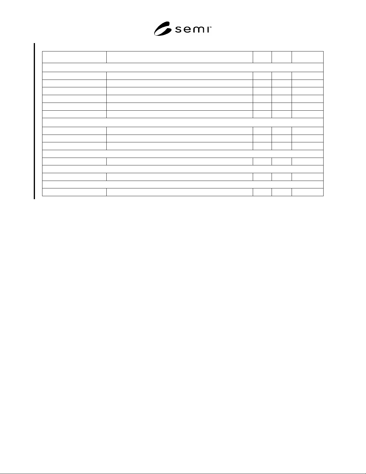
Table 2 DMPM Primitive Functions
DMPM Function Description SSAP DSAP FDL SRV
Master-Slave
Data_Exchange Exchanges I/O Data NIL NIL SRD
Check_Cfg Sends Configuration to DP-Slave for verification. 62 62 SRD
Set_Prm Sends Parametric Data to DP-Slave. 62 61 SRD
Slave_Diag Retrieves the Diagnostic Data Structure from a DP-Slave. 62 60 SRD
Get_Cfg Retrieves the Configuration Data Structure from a DP-Slave. 62 59 SRD
Global_Control Controls the Operational and Synchronization of DP-Slaves. 62 58 SDN
DPM2-Slave
RD_Outp Retrieves the Status of the Outputs of the DP-Slave. 62 57 SRD
RD_Inp Retrieves the Values of the Inputs of the DP-Slave. 62 56 SRD
Set_Slave_Add Sets the Node Address of a DP-Slave. 62 55 SRD
Master-Master
Various Services for Master-Master Communications 54 54 SRD/SDN
Master-Slave — Extended Communications
Read/Write Acyclic Read/Write of DP-Slave Data 51 51 SRD
DPM2-Slave — Connection Configuration
Initiate/Read/Write ... Services for Control and Management of the MS2 Connection 50 x..49 SRD
6.4.7 Service Access Point (SAP)
6.4.7.1 The Service Access Point provides standard access addressing for messages. The FDL message frame
includes fields for Source and Destination SAP. By directing a message to a particular Destination SAP, its context
is immediately known. This provides a fast and interoperable environment for device messaging.
6.4.8 Device Profile/Device Data Base
6.4.8.1 PROFIBUS devices have different performance characteristics. Features differ in regard to available
functionality (i.e., number of I/O signals and diagnostic messages) or possible bus parameters such as baud rate and
time monitoring. These parameters vary individually for each device type and vendor. These parameters are usually
documented in the technical manual. To achieve simple plug-and-play configuration of PROFIBUS, the
characteristic features are specified in an electronic data sheet called a Device Data Base file or GSD file.
6.4.8.2 The GSD Files provide a clear and comprehensive description of the characteristics of a device type in a
precisely defined format. These are prepared individually by the vendor for each type of device and made available
to the user in the form of a Device Data Base Sheet and a GSD File. The device data base file is divided into three
parts: General Specifications, Master Related Specifications, and Slave Related Specifications.
6.4.8.3 These GSD Files are maintained and managed by the PROFIBUS Trade Organization.
6.5 Network Management
6.5.1 The PROFIBUS-DP system is managed through several phases of operation. A Master device must have
knowledge of the Device Profile for each of the Slave devices it will connect. The Device Data Base Files serve this
purpose. Upon initialization, a Master will control a DP-Slave through three operational modes: Parameterization,
Configuration, and I/O Data Exchange. In any operational mode, a Master may interrogate a DP-Slave for its
Diagnostic information.
6.5.2 In the sections that follow, these operation modes are mapped to related SAN CDM behavior states.
7 Required Object Types
7.1 This section describes a general mapping of the SEMI SAN Object Model to the PROFIBUS-DP environment.
Component definitions are clarified and the mapping of Attributes, Services, and Behaviors are specified.
SEMI E54.8-0305 © SEMI 1999, 2005 8
7.2 Object Model
7.2.1 The Object Model defined in the CDM is represented in the PROFIBUS NCS. Specifically, the DM and SAC
objects are mapped.
7.2.2 The CDM Objects are mapped to slots. These slots have a unique address space within the device. The
Application Objects associated with the SDM standards are mapped in PROFIBUS-DP Device Data Base
documents as defined above in the Device Profile/Device Data Base section. §9 specifies the mapping of SDM
Objects in PROFIBUS-DP.
7.3 Component Mapping Summary
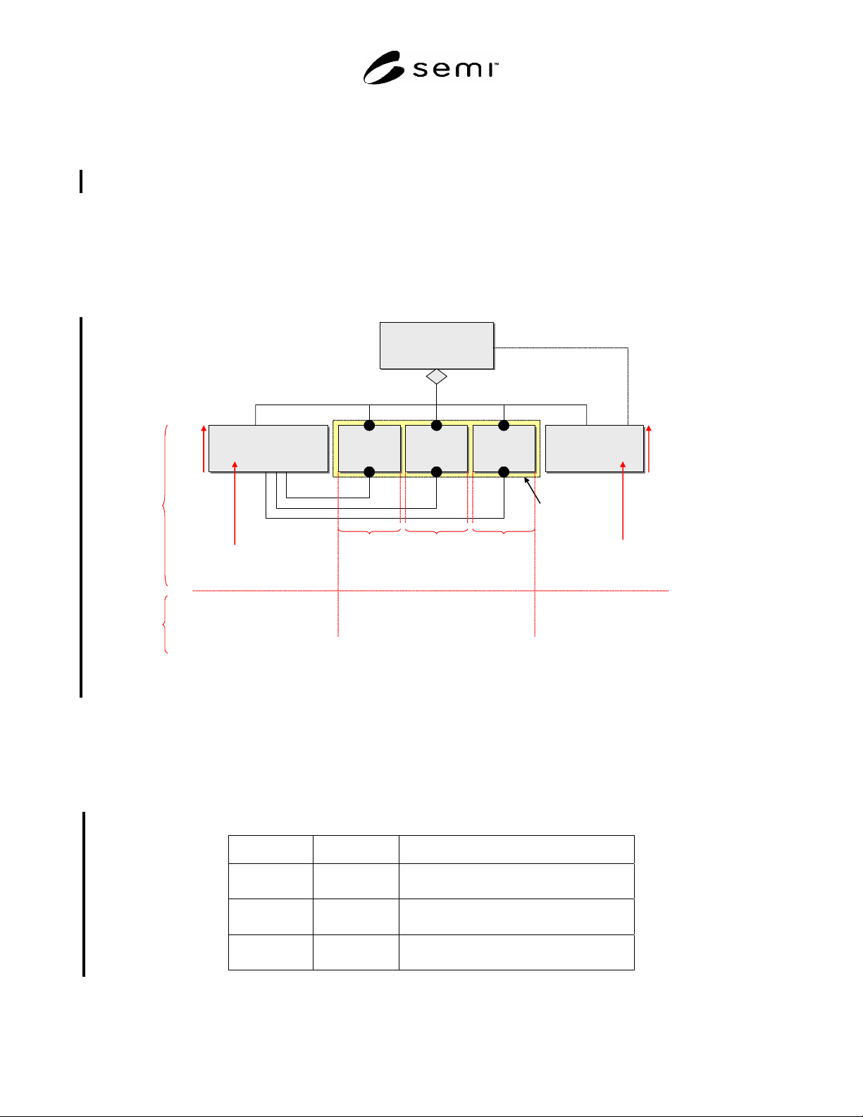
7.3.1 Figure 2 provides a summary of the components of the CDM object model as they relate to the components of
PROFIBUS-DP.
Device
Device
Sensor/Actuator/
Controller Object
(SAC)
Sensor/Actuator/
Controller Object
(SAC)
Sensor
Object(s)
Sensor
Object(s)
Actuator
Object(s)
Actuator
Object(s)
Controller
Object(s)
Controller
Object(s)
Device Manager
Object
(DM)
Device Manager
Object
(DM)
is managed by
(Aggregation)
coordinates
m + n + p * 1
mn p
mn p
Active Element
Slot 0
Slot 0
1 Slot
per object,
starting with
Slot 1
1 Slot
per object,
starting with
Slot m+1
1 Slot
per object,
starting with
Slot m+n+1
Index
64
95
other Services
Cyclic
Services
Cyclic Data Structures will
be defined by Device Families
(Profiles) and via GSD
Figure 2
Component Mapping Summary
7.4 Objects
7.4.1 The required objects of the CDM are identified here. Additional objects that are contained in the SDM are
given identifiers in the Device Profile. §9 specifies additional mapping information.
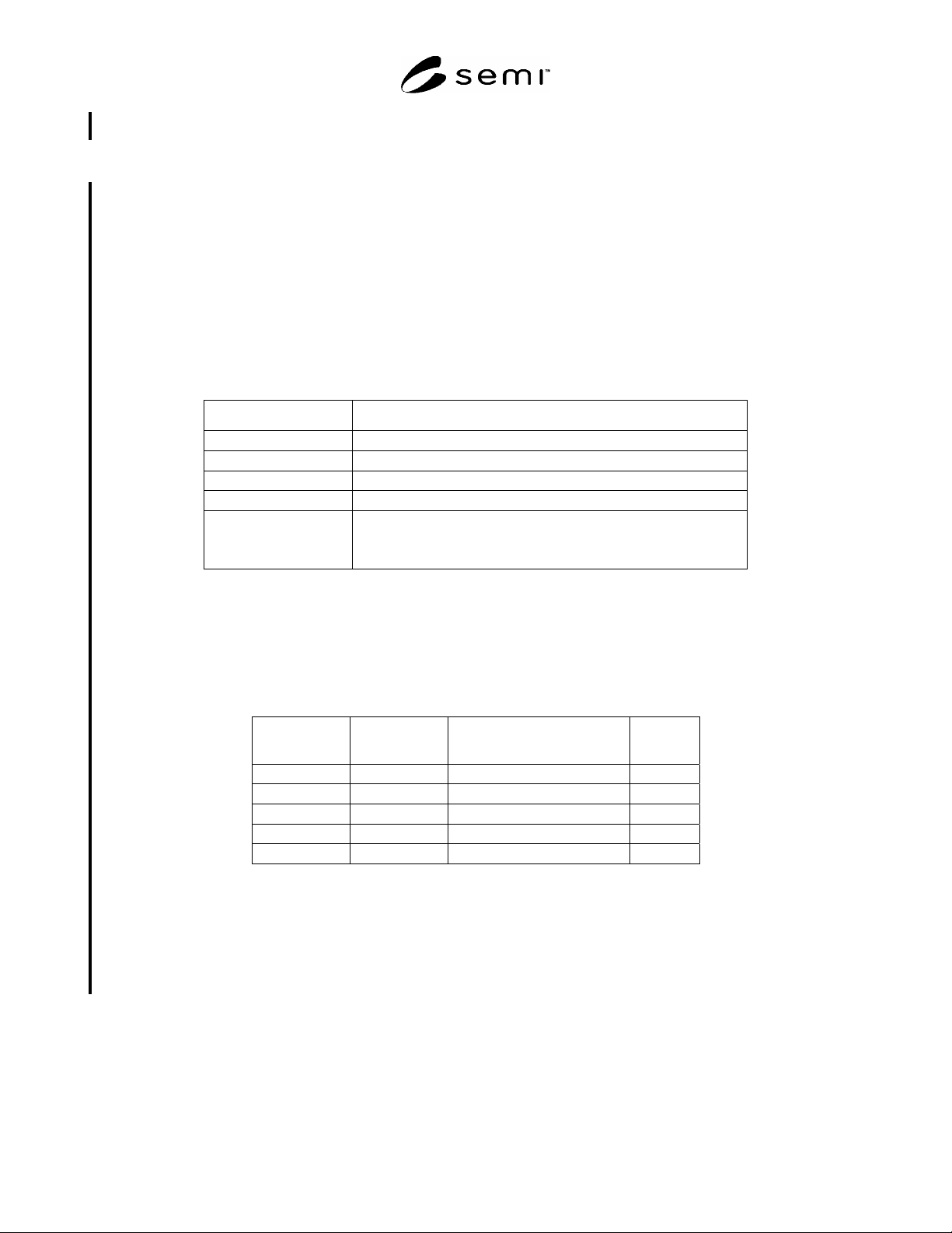
7.4.2 Table 3 lists the Object Identifiers specified for use in protocol messages. Slot numbers are the way for
addressing Objects within PROFIBUS-DP.
Table 3 Object Identifiers
Slot ID Index Object
0 IM0-17
96
DM Object
DM Control
0 64
65–95
SAC Control
SAC Object
1–n 32–254 Application Objects as specified
in §§ 7 and 9.
SEMI E54.8-0305 © SEMI 1999, 2005 9
7.4.3 Assembly Objects and Local Link Objects which are objects embedded in the SAC Object is not explicitly
mapped.
7.5 Attributes
7.5.1 General
7.5.1.1 All attributes are accessible via Get_Attribute and Set_Attribute services defined in the sections below.
Additionally, attributes are accessible via different PROFIBUS-DP defined methods which are mapped in this
document based on attribute type.
7.5.2 DM Attributes
7.5.2.1 All attributes are communicated with Read and Write Service and mapped to IM Blocks. Status attributes
are modeled additionally as Channel Diagnosis. See Table 18 for detailed mapping.
7.5.2.2 Table 4 shows the DM status attribute mapping to Diagnosis.
Table 4 Channel Diagnosis mapping of DM Status
Parameter Value
Identifier_Number = SlotID of the Object
Channel_Number 0 = Global
Channel Type 0 = unspecified
IO Type 0 = unspecified
Error Type 9 = Error with Bit0 - 6 set in Common Exception Detail 1
21 = Error Calibration set in Common Exception Detail Attribute 1
17 = Error with Bit set in Common Exception Detail 2
7.5.3 SAC Attributes
7.5.3.1 The attributes of SAC are mapped to Process data objects of PROFIBUS.
7.5.3.2 The Slot number used is 0. The index is the numeric value of the SAC Attribute identifier with an offset of
64 (see Table 5).
Table 5 SAC Object Attribute Identifiers
SEMI CDM
Attribute ID
PROFIBUS
Index
Attribute Detail
SacA1 65 Last Calibration Date
SacA2 66 Next Calibration Date
SacA3 67 Expiration Timer
SacA4 68 Expiration Warning Enable
SacA5 69 Run Hours
7.5.4 Active Element Attributes
7.5.4.1 The attributes of Active Elements are mapped to Process data objects of PROFIBUS. These attributes are
contained in any Sensor, Actuator and Controller Object.
7.5.4.2 The Slot number used is the instance number in the device. The index is the numeric value of the Active
Element Attribute identifier with an offset of 64 (see Table 6).