semi合集-English.pdf - 第507页
SEMI E73-0301 © SEMI 1998 , 2001 4 Table 5 Control S ignal Connect or (pump side) No. Items Connector Type Re ferenced S tandard Pin Assi gnments Remarks 1 Control a nd r unning status signals 15 pin D sub-m iniature Fem…
SEMI E73-0301 © SEMI 1998, 20013
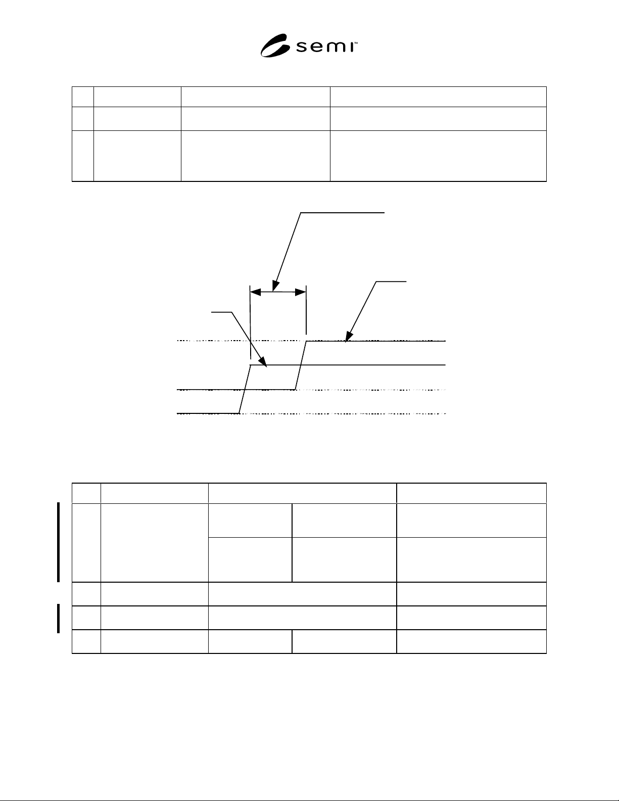
Table 3 Response Time for Signals
No. Items Acceptable Response Time Remarks
1 Input Power ON Under 10 seconds
After input power turns on
Objects:
All status signals shall be ready.
2 Control Signals Under 2 seconds
After receiving a signal
See Figure 2
Objects:
a) Start signal (input) ->> Start status (output)
b) Stop signal (input) ->>Stop status (output)
Under 2 seconds
close
open
open
close
Start status
(output)
Supplied: Start/Stop signal
(input)
(Response time for the
control signals)
Figure 2
Example of Response Time for Start Signal and Start Status
Table 4 Signal Power and Contacts
No. Items Power Remarks
Input signals to DRP
(Control signal)
Input signals shall be
driven by the DC power
supply in DRP.
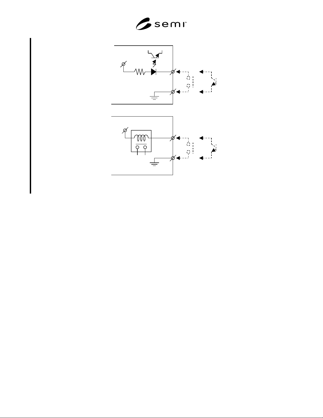
Example: See Figure 4.
a) Photocoupler Input.
b) Relay Input.
1 Signal power supply
Output signals from
DRP (Running status
signal)
Output signals shall be
driven by DC power
supply in tools.
Example: See Figure 5.
a) To photocoupler unit.
b) To relay unit.
c) To TTL unit.
2 Signal power supply
voltage
Signal power supply voltage is between 5 V
DC
and 24 V
DC
3 Acceptable range of signal
power supply voltage
Acceptable voltage range is 4 V
DC
minimum, and
30 V
DC
maximum.
4 Running status signal
contact
Dry contact or open
collector
Acceptable current
100 mA maximum.
SEMI E73-0301 © SEMI 1998, 2001 4
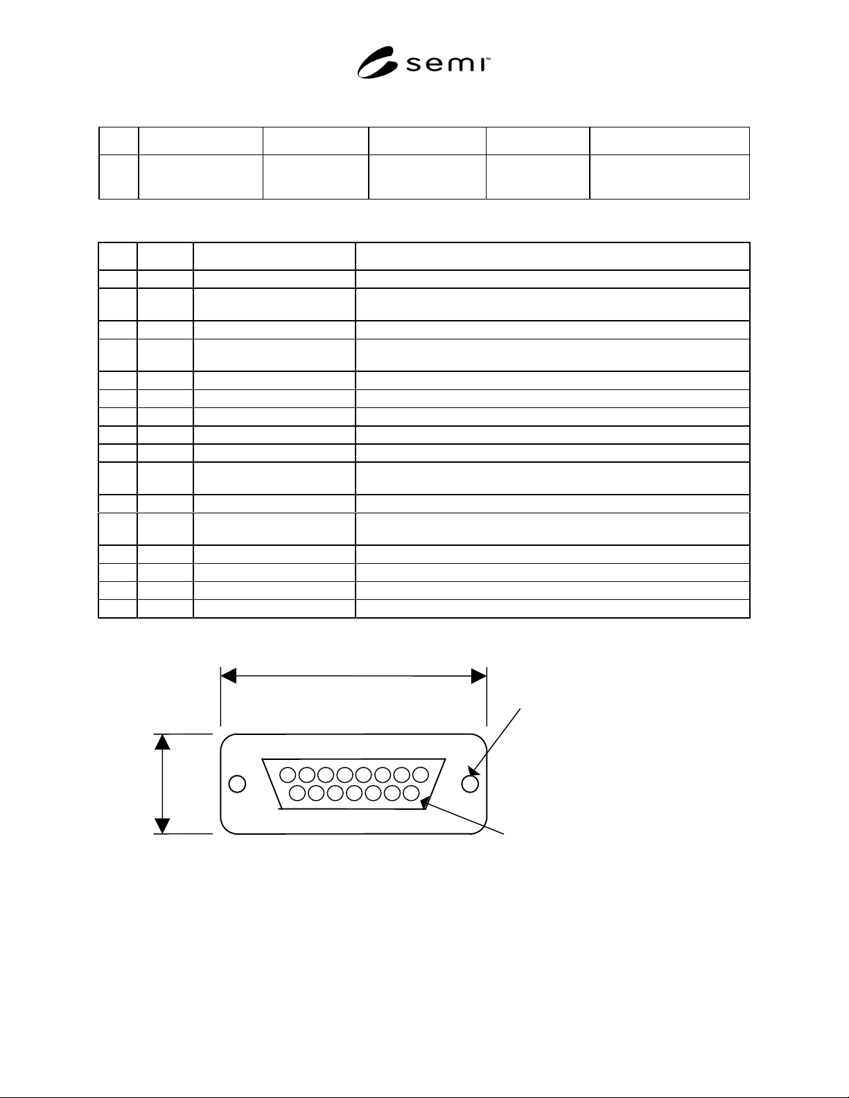
Table 5 Control Signal Connector (pump side)
No. Items Connector Type Referenced Standard Pin Assignments Remarks
1
Control and running
status signals
15 pin
D sub-miniature
Female receptacle
See Table 6 and
Figure 3
See Related Documents for an
example of the specifications
for this connector type.
Table 6 Pin Assignment for Control Signal Connector
No. Pin No. Signal item (polarity) Remarks
1 1 DRP start input ( + )
2 2 (MBP start input) ( + ) An upper pump, such as mechanical booster pump (MBP), to be used with
dry pump systems.
3 3 DRP start/stop status ( + )
4 4 (MBP start/stop status) ( + ) An upper pump, such as mechanical booster pump (MBP), to be used with
dry pump systems.
5 5 Warning status ( + )
6 6 Alarm status ( + )
7 7 Remote/Local status ( + )
88
9 9 DRP start input ( - )
10 10 (MBP start input) ( - ) An upper pump, such as mechanical booster pump (MBP), to be used with
dry pump systems.
11 11 DRP start/stop status ( - )
12 12 (MBP start/stop status) ( - ) An upper pump, such as mechanical booster pump (MBP), to be used with
dry pump systems.
13 13 Warning status ( - )
14 14 Alarm status ( - )
15 15 Remote/Local status ( - )
16 -
MAX. 45.1 mm
MAX. 18.0 mm
Screw lock size : M2.6
Contact pin surface : Au
8
1
9
15
Figure 3
15 pin D Sub-Miniature Female Receptacle
SEMI E73-0301 © SEMI 1998, 20015
DC Voltage
DC Voltage
ToolDRP
(+)
(-)
(+)
(-)
DRP Tool
b
)
a
)
Figure 4
Schematic Example of DRP Input Signals