semi合集-English.pdf - 第6921页
SEMI S8-0705 © SEMI 1995, 2005 18 Section Indicator Acceptance Criteria Metric Units (US Customary Units) Actual Conforms/Does N ot Conform/Not Applicable 10.2.5 Horizontal leg clearan ce, wi dth. minimum 610 mm (24 in.)…
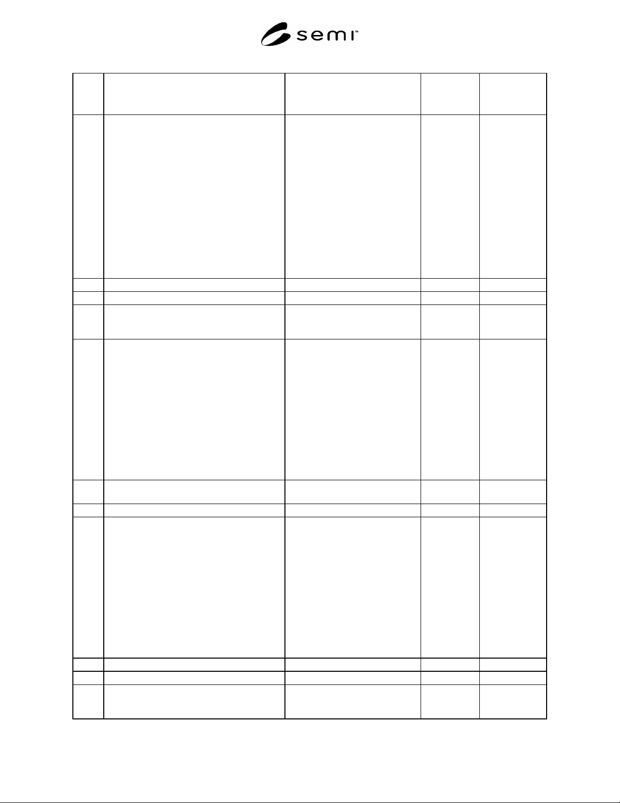
SEMI S8-0705 © SEMI 1995, 2005 17
Section Indicator
Acceptance Criteria
Metric Units (US Customary Units)
Actual
Conforms/Does
N
ot Conform/Not
Applicable
9.2.2 Location of frequently used controls. Maximum
reaches are indicated for various heights.
Reaches are measured from the leading edge of
the work surface or obstacle. Controls should
not be located above 1067 mm (42 in.) or below
762 mm (30 in.). Interpolate for intermediate
values.
Height of 1067 mm (42 in.)
Height of 1016 mm (40 in.)
Height of 965 mm (38 in.)
Height of 914 mm (36 in.)
Height of 864 mm (34 in.)
Height of 813 mm (32 in.)
Height of 762 mm (30 in.)
reach 330 mm (13.0 in.)
reach 368 mm (14.5 in.)
reach 394 mm (15.5 in.)
reach 406 mm (16.0 in.)
reach 419 mm (16.5 in.)
reach 419 mm (16.5 in.)
reach 419 mm (16.5 in.)
10 Workstation Design
10.1 Standing station
#1
10.1.1 Work surface edge radius where the operator
can assume a static posture in contact with the
edge.
minimum 6.4 mm (0.25 in.) radius
10.1.2 Height of keyboard, trackball, or mouse (to
home row, top of ball/mouse).
NOTE: In applications where input devices
(keyboard, trackball, or mouse) are used more
like machine controls (intermittent one finger
entry on the keyboard, intermittent short term
use of the mouse or trackball) than for standard
typing (continuous use of keyboard for entry of
long character strings, extended use of trackball
or mouse in graphical environment), it is
appropriate to use the height and reach locations
described in §9, Hand Control Location
(standing station).
maximum 1020 mm (40 in.)
minimum 970 mm (38 in.)
10.1.3 Height of microscope eyepieces. Should be
adjustable through at least this range.
Range includes 1270 mm (50 in.) to
1730 mm (68 in.)
10.2 Seated station
#2
10.2.1 Height of keyboard, trackball, or mouse. (to
home row, top of ball/mouse).
NOTE: In applications where input devices
(keyboard, trackball, or mouse) are used more
like machine controls (intermittent one finger
entry on the keyboard, intermittent short term
use of the mouse or trackball) than for standard
typing (continuous use of keyboard for entry of
long character strings, extended use of trackball
or mouse in graphical environment), it is
appropriate to use the height and reach locations
described in §9, Hand Control Location (seated
station).
maximum 760 mm (30 in.)
minimum 710 mm (28 in.)
10.2.2 Vertical leg clearance. minimum 673 mm (26.5 in.)
10.2.3 Horizontal leg clearance, depth at knee level. minimum 508 mm (20 in.)
10.2.4 Horizontal leg clearance, depth at foot level. minimum 660 mm (26 in.) depth ×
254 mm (10 in.) vertical foot
clearance
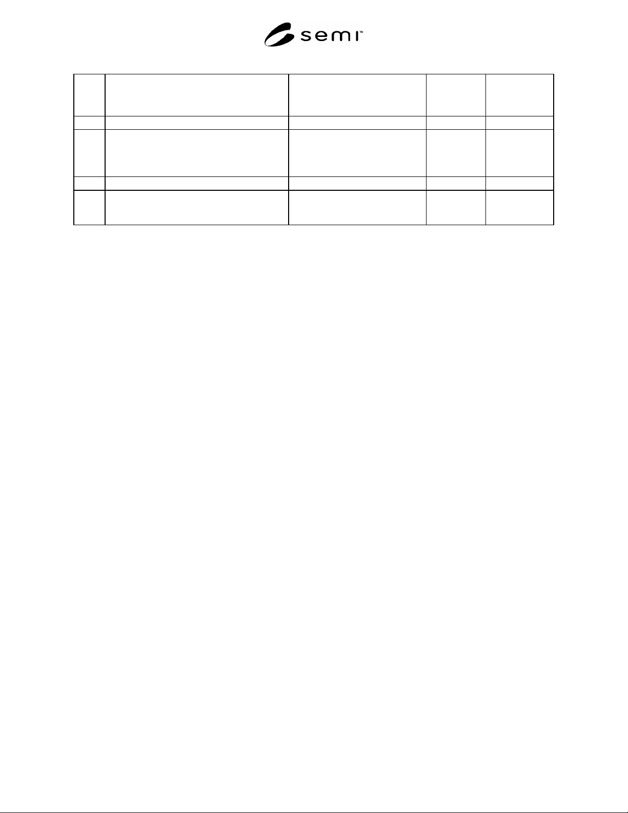
SEMI S8-0705 © SEMI 1995, 2005 18
Section Indicator
Acceptance Criteria
Metric Units (US Customary Units)
Actual
Conforms/Does
N
ot Conform/Not
Applicable
10.2.5 Horizontal leg clearance, width. minimum 610 mm (24 in.)
10.2.6 Height of microscope eyepiece. Should be
adjustable through at least this range.
Note: Assumes a 711 mm (28 in.) to 762 mm
(30 in.) worksurface.
Range includes 1220 mm (48 in.) to
1370 mm (54 in.)
10.2.7 Thickness of work surface. maximum 51 mm (2.0 in.)
10.2.8 Work surface edge radius where the operator
can assume a static posture in contact with the
edge.
minimum 6 mm (0.25 in.) radius
#1
A standing station is one where the operator can assume a standing posture or a seated posture in a tall stool which places the operator at
approximately the same stature.
#2
A seated station is one where a short cylinder office style chair is used.
#3
Distance measured away from the equipment or obstruction for body clearance in the given posture.

SEMI S8-0705 © SEMI 1995, 2005 19
APPENDIX 2
LIFTING, STRENGTH, AND MATERIALS HANDLING
NOTICE: The material in this appendix is an official part of SEMI S8 and was approved by full letter ballot
procedures by the North American Regional Standards Committee.
A2-1 General Considerations
A2-1.1 For recommended guidelines regarding the percentage of a user's maximum grip strength to be exerted in
execution of a task see Related Information 1, Table R1-3.
A2-1.2 Where standard product or containers are to be handled at equipment load and unload stations,
mechanization should be considered for orientation and handling. Where manual handling is necessary, the design
should reduce extended reaching, lifting, pulling, and awkward postures. Simultaneous lifting and twisting should be
avoided. Load, unload, and lift over points should be located such that the floor to hand height is 84–107 cm
(33–42 in.), optimal design target is 102 cm (40 in.).
A2-1.3 Handles or cutouts should be designed to facilitate use of the power grip (e.g., similar to that used to hold a
pistol). Avoid handles that require pinch grips or awkward postures. Handles should allow carrying close to the
body.
A2-1.4 Lifting and handling tasks performed in a stooping position should be avoided. Stooping occurs when the
vertical material handling height is less than 84 cm (33 in.), or the horizontal reach distance is greater than 46 cm
(18 in.) in front of body.
A2-1.5 For two handed push/pull activities the floor to hand height should be between 97 cm (38 in.) and 112 cm
(44 in.).
A2-1.6 Consideration should be given to the standing surface to minimize the risk of slips and falls.
A2-1.7 Awkward postures should be avoided. Refer to Related Information 1, Table R1-2 for a list of
recommended ranges of awkward postures to avoid.
A2-1.8 For a 2-person handling task, there should be adequate coupling locations and adequate body clearance for
the activity. Analyses need to be performed and documented for each person lifting if any of the parameters
(e.g., horizontal reach) are different.
A2-2 Selecting and Using the Appropriate MMH Analysis Tool(s)
A2-2.1 Three general MMH evaluation tools are identified in the following matrix. The three tools are the
“Application manual for the Revised NIOSH Lifting Equation” lifting equation, biomechanical models, and
psychophysical capacity tabular data. Table A2-1 was designed to assist in determining which analysis tools are
appropriate for a particular task. For each unique characteristic of the task, a checkmark in the analysis tool column
indicates that the analysis tool is appropriate. If there is any aspect of the task that does not show a check mark in a
particular tools column, that analysis tool is not appropriate to evaluate the task. Note that in many situations
multiple tools are appropriate. In situations where the 1991 NIOSH equation is appropriate, the assessor should use
it, because it typically will provide the most conservative results. In other situations, the assessor may use any of the
appropriate tools.
A2-2.2 Correct application of the 1991 NIOSH equation is described in Waters, Thomas, et. al., Application manual
for the Revised NIOSH Lifting Equation, U.S. Department of Health and Human Services (NIOSH), Cincinnati,
OH, 1994.
A2-2.3 There are many sources of psychophysical data. One such source is A. Mital, A.S. Nicholson, M.M. Ayoub,
A Guide to Manual Materials Handling, Taylor and Francis, London, 1993.
A2-2.4 Biomechanical analysis can be completed using biomechanical modeling software.