semi合集-English.pdf - 第2619页
SEMI E94-0705 © SEMI 2000, 2005 2 5.1.3 equipment — the intelligent syste m that communicates with the host. 5.1.4 host — the intelligent system that communicates with the equipment. 5.1.5 life cycle — the processes and …

SEMI E94-0705 © SEMI 2000, 2005 1
SEMI E94-0705
SPECIFICATION FOR CONTROL JOB MANAGEMENT
This specification was technically approved by the global Information & Control Committee. This edition
was approved for publication by the global Audits and Reviews Subcommittee on April 7, 2005. It was
available at www.semi.org in June 2005 and on CD-ROM in July 2005. Originally published February 2000;
previously published November 2004.
1 Purpose
1.1 This specification describes equipment provided services to the factory that supports a high level of factory
automation. These services provide capabilities for the host to coordinate processing and disposition of materials on
production equipment.
2 Scope
2.1 This specification may be applied to equipment that is compliant to SEMI E30 (GEM). However, it is also
intended that this standard will be useful for future generation equipment interfaces that supercede SEMI E30, such
as SEMI E53.
NOTICE: This standard does not purport to address safety issues, if any, associated with its use. It is the
responsibility of the users of this standard to establish appropriate safety and health practices and determine the
applicability of regulatory or other limitations prior to use.
3 Limitations
3.1 This standard presents a model of the ControlJob. The model delineates the services (messages) and behavior
of the ControlJob. The model is protocol independent. Thus, an ancillary standard must be selected in order to
provide a complete implementation.
3.2 This standard should not be applied to non-production equipment, such as, material transport systems or
facilities (environmental) controllers.
3.3 This specification applies to equipment for which the atomic unit of material is the same for all input and output
carriers on the equipment. It may not apply to equipment which would perform operations such as slicing or
assembly that would require or result in different input and output material objects. This specification may not
apply to equipment or equipment configurations where the equipment does not handle carriers, as in the case of a
stepper or scanner in a linked photolithography cell.
4 Referenced Standards and Documents
4.1 SEMI Standards
SEMI E30 — Generic Model for Communications and Control of Manufacturing Equipment (GEM)
SEMI E39 — Object Services Standard: Concepts, Behavior, and Services
SEMI E40 — Standard for Processing Management
SEMI E53 — Event Reporting
NOTICE: Unless otherwise indicated, all documents cited shall be the latest published versions.
5 Terminology
5.1 Definitions
5.1.1 control job — defines a unit of work on equipment for one or more carriers. The work is described by a set of
one or more process jobs to be applied to the material contained in the carriers.
5.1.2 de-queue — the act of removing an item from a queue. The de-queue implies nothing about the status of the
item after removal.

SEMI E94-0705 © SEMI 2000, 2005 2
5.1.3 equipment — the intelligent system that communicates with the host.
5.1.4 host — the intelligent system that communicates with the equipment.
5.1.5 life cycle — the processes and activities of something from its beginning (creation) to its ending.
5.1.6 multi-module equipment — equipment that has more than one distinct processing resource (e.g., chamber).
5.1.7 production equipment — equipment that measures or adds value to the product.
5.1.8 protocol independent — for software, this means that the message descriptions are independent of delivery
mechanisms.
5.1.9 set-up — a description of the current process capability of an equipment.
5.1.10 substrate — basic unit of material on which work is performed to create a product. Examples include
wafers, lead frames, CD’s, die, flat panel displays, circuit boards, and disks.
5.1.11 substrate port — the carrier location from which substrates are accessed by the equipment.
5.1.12 uni-carrier — term for an equipment mode of operation in which all material is returned to the source carrier
after processing.
5.1.13 user start — activities that are initiated on a system by another system or operator.
6 Conventions
6.1 Object Models
6.1.1 This standard uses object models to specify the control job interface.
6.1.2 Object Services Standard
6.1.2.1 This document conforms to the conventions established by SEMI E39.
6.1.3 Formal Name of an Object
6.1.3.1 The text capitalizes formal object name references, similar to the way capitalization is normally used when
discussing entities. When describing something in the general (like cities) lower case is used, but when a specific
entity is of interest (New York City), then first letters are capitalized.
6.2 State Model Methodology
6.2.1 This document uses the Harel state chart convention for describing dynamic operation of defined objects. The
outline of this convention is described in an attachment of SEMI E30. The official definition of this convention is
described in “State Charts: A Visual Formalism for Complex Systems” written by D. Harel in Science of Computer
Programming 8, 1987.
1
6.2.2 The Harel convention does not have the concept of state models of “creation” and “extinction” for expressing
a temporary entity. The “job” described in this document is such an entity, and a copy of the same state model is
used for an independent job newly created. In this document, a circle with a black circle inside is used for
expressing extinction of an entity. A filled, black circle denotes the entry to the state model (the entity creation).
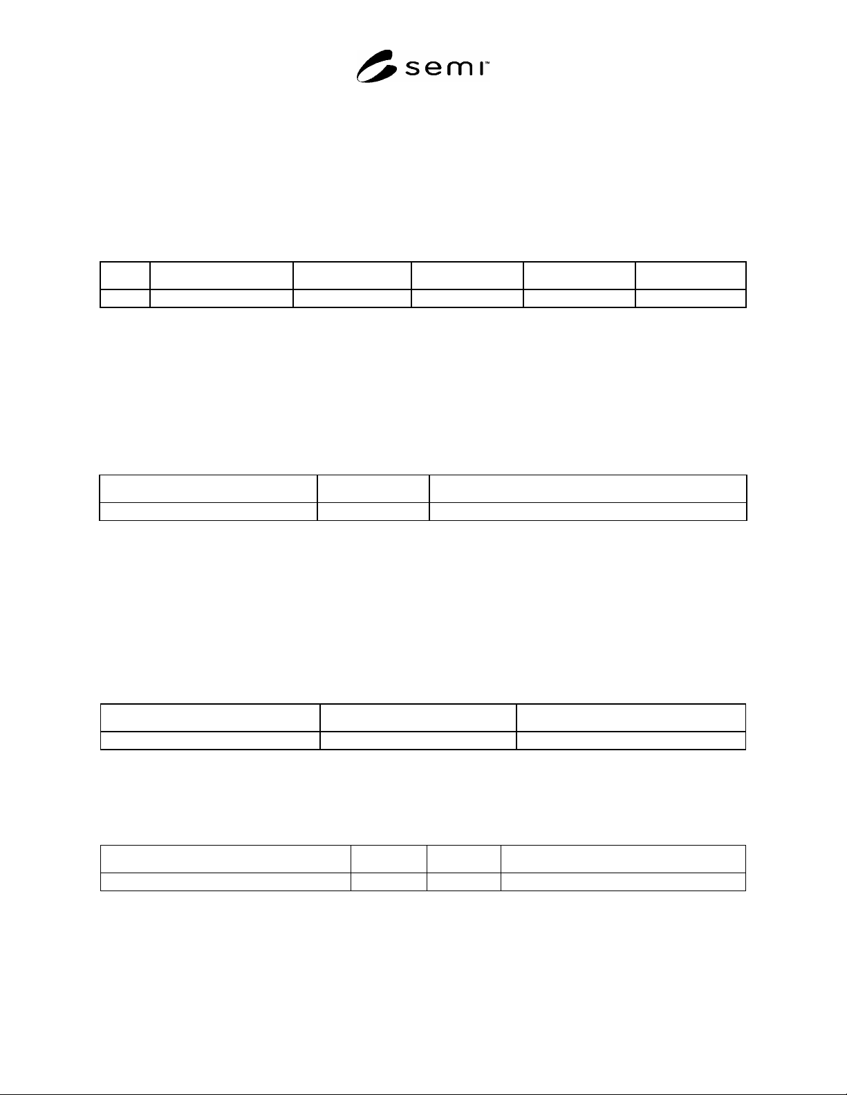
6.2.3 Transition tables are provided in conjunction with the state diagrams to explicitly describe the nature of each
state transition. A transition table contains columns for Transition number, Previous State, Trigger, New State,
Actions, and Comments. The “trigger” (column 3) for the transition occurs while in the “previous” state. The
“actions” (column 5) includes a combination of:
1) Actions taken upon exit of the previous state.
2) Actions taken upon entry of the new state.
3) Actions taken which are most closely associated with the transition.
6.2.3.1 No differentiation is made between these cases.
1 Elsevier Science, P.O. Box 945, New York, NY 10159-0945, http://www.elsevier.nl/homepage/browse.htt
SEMI E94-0705 © SEMI 2000, 2005 3
6.2.4 The state models included in this standard are a requirement for Control Job Management compliance. A
state model consists of a state model diagram, state definitions, and a state transition table. When using collection
events, all state transitions in this standard, unless otherwise specified, shall correspond to collection events.
6.2.5 A state model represents the host’s view of the equipment, and does not necessarily describe the internal
equipment operation. When using collection events, all Control Job Management state model transitions shall be
mapped sequentially into the appropriate internal equipment collection events that satisfy the requirements of those
transitions. In certain implementations, the equipment may enter a state and have already satisfied all of the
conditions required by the Control Job Management state models for transition to another state. In the case, the
equipment makes the required transition without any additional actions in this situation.
Num Previous State Trigger New State Actions Comments
6.3 Service Message Representation
6.3.1 Services are functions or methods that may be provided by either the equipment or the host. A service
message may be either a request message, which always requires a response, or a notification message, that does not
require a response.
6.3.2 Service Definition
6.3.2.1 A service definition table defines the specific set of messages for a given service resource, as shown in the
following table:
Message Service Name Type Description
6.3.2.2 Type can be either “N” = Notification or “R” = Request & Response.
6.3.2.3 Notification type messages are initiated by the service provider (e.g., the equipment) and the provider does
not expect to get a response from the service user. Request messages are initiated by a service user (e.g., the host).
Request messages ask for data or an activity from the provider. Request messages expect a specific response
message (no presumption on the message content).
6.3.3 Service Parameter Dictionary
6.3.3.1 A service parameter dictionary table defines the description, format and its possible value for parameters
used by services, as shown in the following table:
Parameter Name Description Format: Possible Value
6.3.3.2 A row is provided in the table for each parameter of a service.
6.3.4 Service Message Definition
6.3.4.1 A service message definition table defines the parameters used in a service, as shown in the following table:
Parameter Req/Ind Res/Cnf Comment
6.3.4.2 The columns labeled REQ/IND and RSP/CNF link the parameters to the direction of the message. The
message sent by the initiator is called the “Request”. The receiver terms this message the “Indication” or the request.
The receiver may then send a “Response” which the original sender terms the “ Confirmation”.