semi合集-English.pdf - 第4184页
SEMI F70-0302 © SEMI 2002 7 A PPENDIX 2 SA M PLE REPORT FORMAT FOR PULSE FLOW PA RTICLE TEST NOTE: This appendix is being balloted as an official pa rt of SEMI F70 by f ull letter ballo t procedures, but the recomm endat…
SEMI F70-0302 © SEMI 2002
6
APPENDIX 1
SAMPLE REPORT FORMAT FOR STATIC FLOW PARTICLE TEST
NOTE: This appendix is being balloted as an official part of SEMI F70 by full letter ballot procedures, but the
recommendation in this appendix are optional and are not required to conform to this standard.
STATIC FLOW PARTICLE TEST REPORT
Line Design Flow
(l/min)
Test Flow (l/min) Sampling Method Total sampling
volume (l)
Total particle
count
Particle Count
(particle/l)
P-N
2
200 300 Partial Sampling 283 3
1.1 × 10
-2
O
2
10 15 Full Sampling 150 2
1.3 × 10
-2
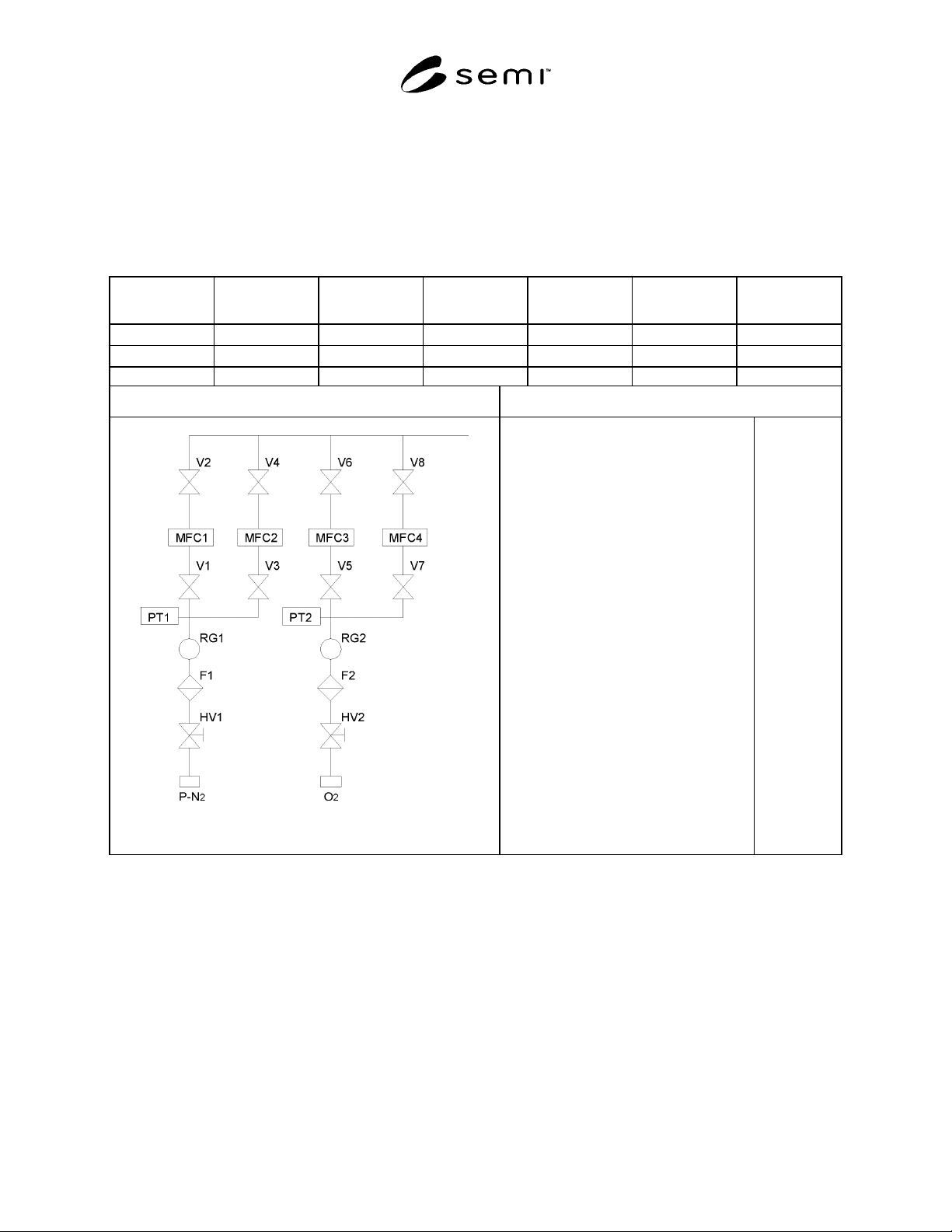
Flow Diagram of System Under Test Test Condition
Counter Type:
Manufacturer of the Counter
Counter Model
Sample Flow:
Particle Diameter:
Sampler Diameter:
Sample Probe Diameter:
Test Gas
Background Count:
LPC
A
B
28.3 l/min
≥ 0.1 µ m
30.0 mm
7.53 mm
LN
2
0
SEMI F70-0302 © SEMI 2002
7
APPENDIX 2
SAMPLE REPORT FORMAT FOR PULSE FLOW PARTICLE TEST
NOTE: This appendix is being balloted as an official part of SEMI F70 by full letter ballot procedures, but the
recommendation in this appendix are optional and are not required to conform to this standard.
PULSE FLOW PARTICLE TEST REPORT
Line Design Flow
(l/min)
Test Flow
(l/min)
Sampling
Method
Total Sampling
Volume (l)
Total Particle
Count
Drive Valve # Particle Count
(particle/l)
4
V1
1.4 × 10
-2
3
V2
1.1 × 10
-2
3
V3
1.1 × 10
-2
P-N
2
200 300
Partial
Sampling
141.5
4
V4
1.4 × 10
-2
1
V5
3.5 × 10
-2
1 V6
3.5 × 10
-2
0 V7 0
O
2
0.5 0.75 Full Sampling
28.5
(See NOTE 1.)
1 V8
3.5 × 10
-2
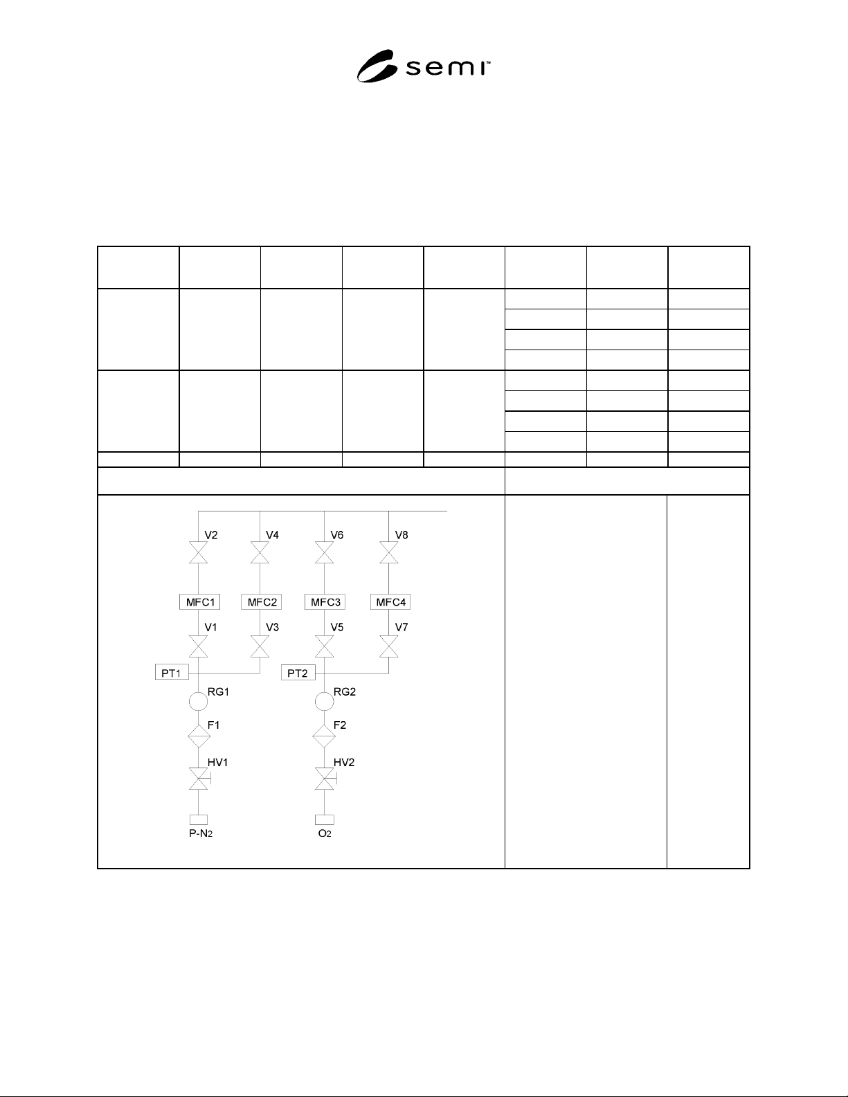
Flow Diagram of System Under Test Test Condition
Counter Type:
Manufacturer of counter
Counter Model
Sample Flow:
Particle Diameter:
Sampler Diameter:
Sample Probe Diameter:
Test gas:
Background Count
Valve Operation Interval:
LPC
A
B
28.3 l/min
≥ 0.1 µ m
30.0 mm
7.53 mm
LN
2
0
30 cycle/
minute
NOTE 1. The test period for O2 line was extended to 76 minutes in order that the total volume of the test flow achieves more than 28.3 liters.

SEMI F70-0302 © SEMI 2002
8
NOTICE: SEMI makes no warranties or representations as to the suitability of the standards set forth herein for any
particular application. The determination of the suitability of the standard is solely the responsibility of the user.
Users are cautioned to refer to manufacturer’s instructions, product labels, product data sheets, and other relevant
literature respecting any materials mentioned herein. These standards are subject to change without notice.
The user’s attention is called to the possibility that compliance with this standard may require use of copyrighted
material or of an invention covered by patent rights. By publication of this standard, SEMI takes no position
respecting the validity of any patent rights or copyrights asserted in connection with any item mentioned in this
standard. Users of this standard are expressly advised that determination of any such patent rights or copyrights, and
the risk of infringement of such rights, are entirely their own responsibility.
Copyright by SEMI® (Semiconductor Equipment and Materials
International), 3081 Zanker Road, San Jose, CA 95134 Reproduction o
f
the contents in whole or in part is forbidden, without express writte
n
content of SEMI.