semi合集-English.pdf - 第307页
SEMI E47.1-0305 © SEMI 1997, 2005 22 y2 40 =1 58.0 ±0.5 BI LA TE RAL DAT UM PL ANE x2 51 =13 2 ±1 r67 24 0 [2 4 2 ] (r67=240.0+0 . 0/ -2.0 fo r co nv e yor groov e exam ple) FACIAL DA TUM PL ANE EXAM P LE CONVEYOR GRO…
SEMI E47.1-0305 © SEMI 1997, 2005 21
RELATED INFORMATION 1
NOTICE: This related information is not an official part of SEMI E47.1, and it is not intended to modify or supercede the
official standard. This information was inserted by the North America Physical Interfaces and Carriers Committee to alert the
readers to potential changes to this provisional standard.
R1-1 A revision ballot will be submitted to require the same bottom carrier ID label area as in SEMI E1.9.
R1-2 A revision ballot will be submitted to increase the maximum thickness of the top robotic flange by 3 mm.
R1-3 A design exists for a FOUP and adapter mechanism that holds only one wafer and is supposed to comply with
SEMI E47.1. A new activity to standardize a “One Wafer FOUP” is being considered.
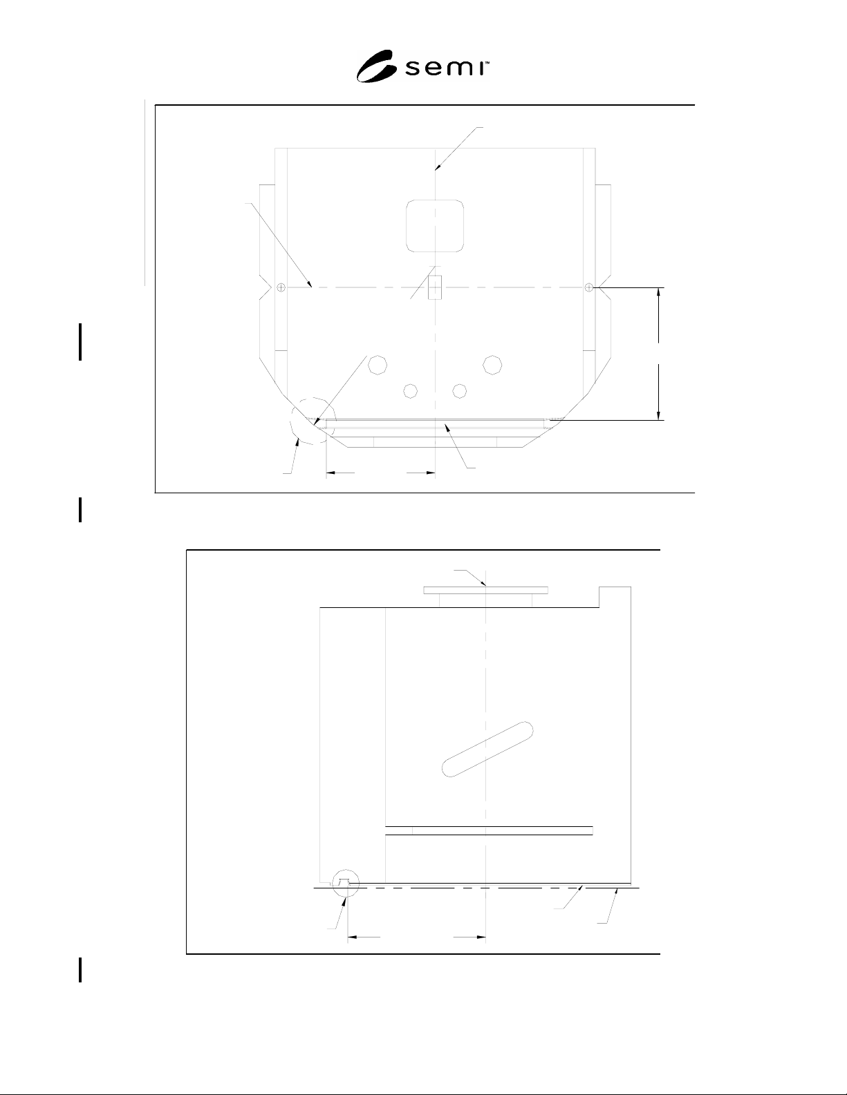
R1-4 Alternate Conveyor Features may be incorporated into FOUPs. One example is a rear conveyor groove. A
Rear Conveyor Groove is defined as below. This design, and/or the application of this design in AMHS systems
may be protected by one or more patents.
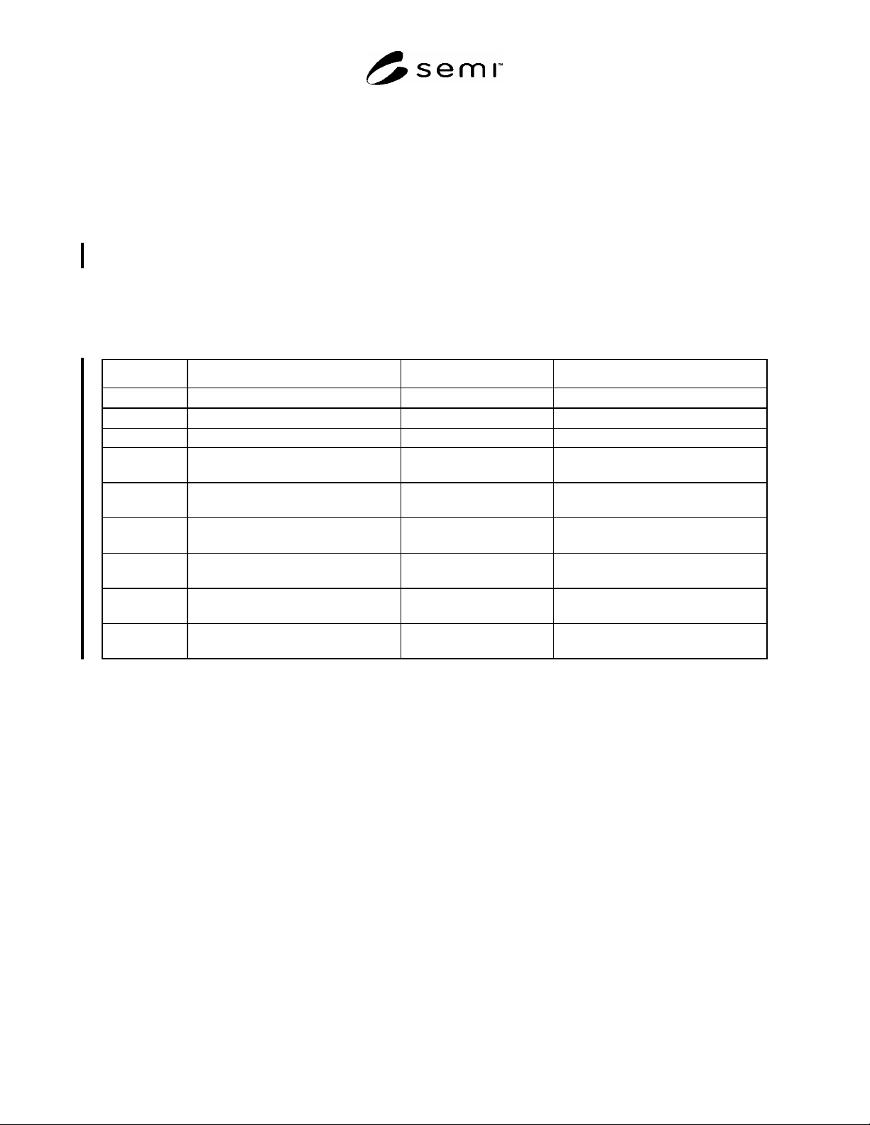
Table R1-1
Symbol Used Value Specified Datum Measured From Feature Measured To
k
17.5 2.5
conveyor groove centerline conveyor groove lead in
k
3 1
conveyor groove centerline conveyor groove lead in
R70k
0.25 mm (0.010 in.) maximum not applicable conveyor groove concave corners
R71k
0.5 mm 0.25mm
(0.02 0.01 in.)
not applicable conveyor groove convex corners
X251k
132.0 1mm
(5.31 0.04 in.)
bilateral datum plane beginning of conveyor groove lead in
Y240k
158.0 0 .5mm
(6.142 0.020 in.)
facial datum plane conveyor groove side closest to facial
datum plane
Y241k
8.50 0.25mm
(0.335 0.0 in.)
conveyor groove side
closest to facial datum plane
conveyor groove side furthest from
facial datum plane
Z314k
5.00 0.25mm
(0.236 0.010 in.)
horizontal datum plane top surface of conveyor groove
Z315k
1.3 0.5mm
(0.052 0.020 in.)
top surface of conveyor
groove
beginning of conveyor groove lead in
radius
SEMI E47.1-0305 © SEMI 1997, 2005 22
y240
=158.0±0.5
BILATERAL DATUM PLANE
x251=132±1
r67240
[242]
(r67=240.0+0.0/-2.0
for conveyor
groove example)
FACIAL DATUM
PLANE
EXAMPLE
CONVEYOR GROOVE
Example Conveyor Groove
Lead In Detail- See Fig. R4-4
Figure R1-2
Bottom View of FOUP Showing Example Conveyor Groove
HORIZONTAL DATUM PLANE
Example Conveyor Groove
Lead In Detail- See Fig. R4-4
y240=158.0±0.5
FACIAL DATUM PLANE
FOUP BOTTOM
SURFACE
Figure R1-3
Side View of FOUP Showing Example Conveyor Groove Feature
SEMI E47.1-0305 © SEMI 1997, 2005 23
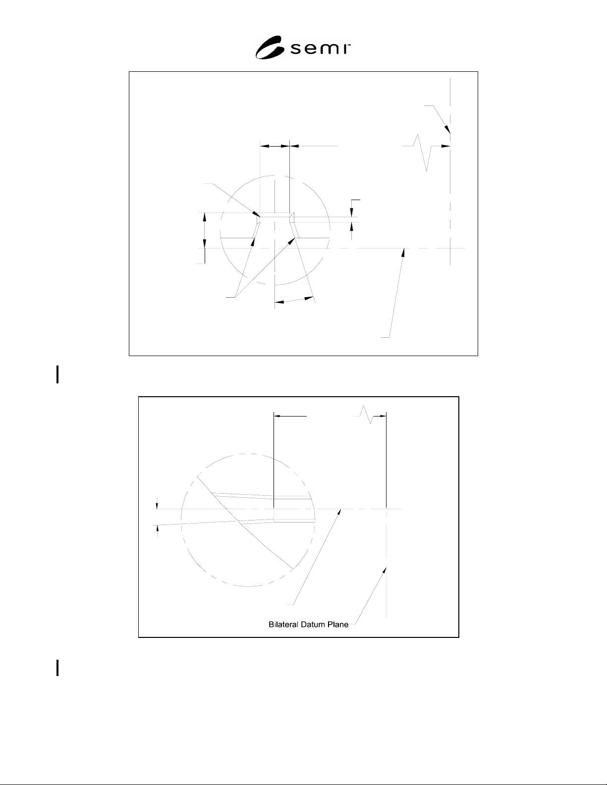
z314=
5.00±0.25
y241=8.5±0.25
z315=1.3±0.5
y240
=158.0±0.5
Facial Datum Plane
Horizontal Datum Plane
r700.25
(2X)
r71=
0.50±.25
=17.5°±2.5°
Figure R1-4
Side View Detail of Example Conveyor Groove on Bottom of FOUP
=3°±1°
x251=132±1
Example Conveyor
Groove Center Line
Figure R1-5
Example Conveyor Groove on Bottom of FOUP