semi合集-English.pdf - 第66页
SEMI E6-0303 © SEMI 1982, 2003 12 Data Sheet 400 - Electrical Po wer (See SEMI E6 section 12) 400 Electrical Power A B C D E F G H 1 Equipment Component Electrical Power Connection Number Connection Label on Equipment Ut…
SEMI E6-0303 © SEMI 1982, 2003 11
12.2.22 Process Cycle Energy (400AK) — Enter the
total electrical energy consumed during the equipment
processing cycle.
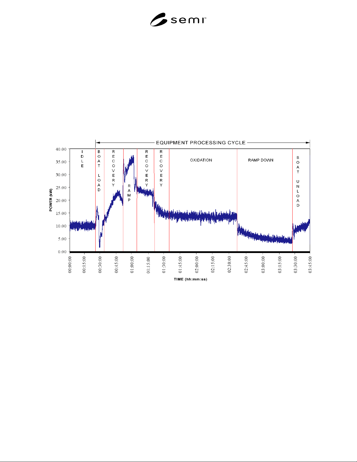
12.2.23 Power Characterization Plot (400AL) — Enter
yes if power consumed through this connection is
represented in the Equipment Power Characterization
Plot provided with this data sheet. If entry is No,
specify reason in Electrical Power Comments cell.
Submit with the electrical power data sheet, a
characterization plot of the one second average true
power demand (kW) versus time for a complete
equipment processing cycle and for equipment idle
condition. This plot should represent the electrical
power demand of the entire equipment (vs. a single
connection). See Figure 1.
12.2.24 Drawing References (400AM) — Enter
references, such as drawing numbers, for any drawings,
schematics, instructions, jigs or fixtures showing this
connection. For example: wiring diagram XXXXX or
voltage sag characterization test report YYYYY. Be
sure to submit referenced material to equipment
purchaser with data sheets.
12.2.25 Electrical Power Comments (400AN) —
Enter
any comments necessary to clarify information given
for this connection.
Figure 1
Equipment Power Characterization Plot
SEMI E6-0303 © SEMI 1982, 2003 12
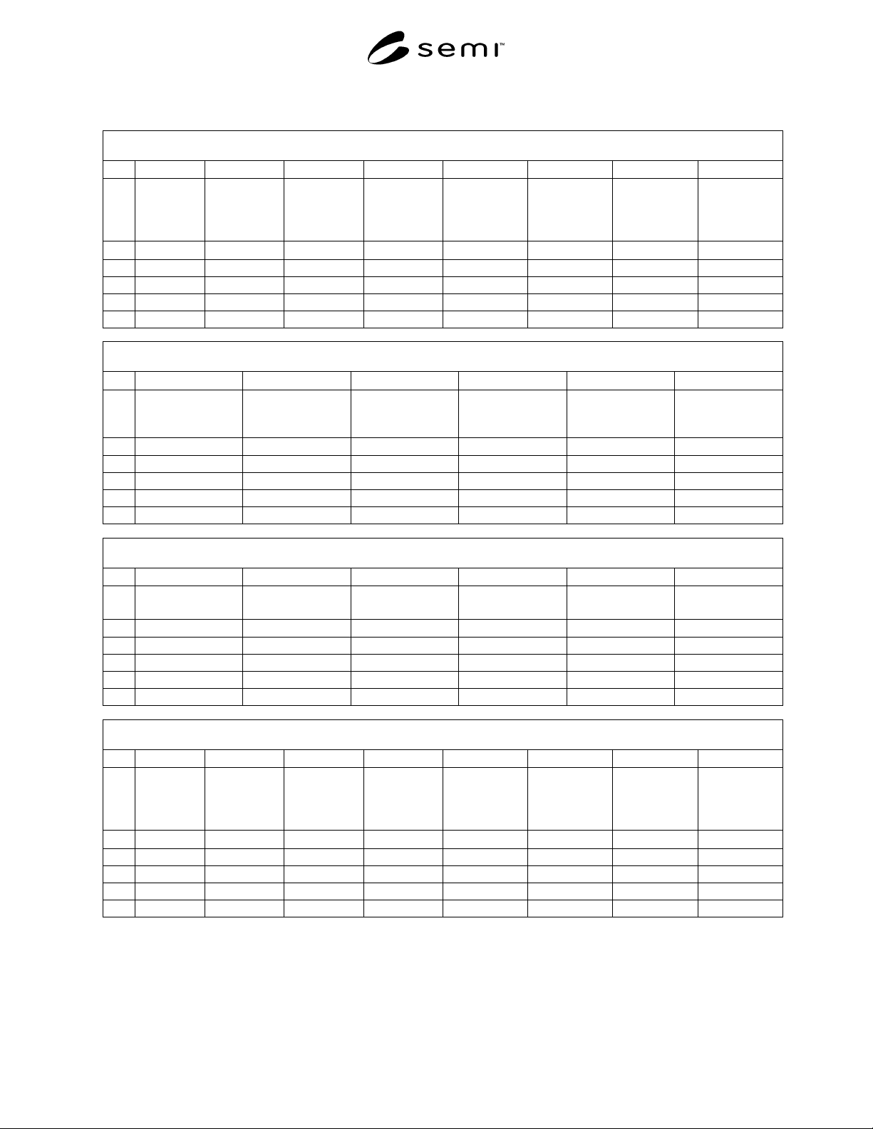
Data Sheet 400 - Electrical Power (See SEMI E6 section 12)
400 Electrical Power
A B C D E F G H
1
Equipment
Component
Electrical
Power
Connection
Number
Connection
Label on
Equipment
Utility
Type
Line Source Voltage/Phase
/Wire
Frequency Equipment
Component
Connection
Type
2
text text text text text text Hz text
3
4
5
6
400 Electrical Power
I J K L M N
1
Ampere
Interrupting
Capacity
Full Load Amps
Phase A
Full Load Amps
Phase B
Full Load Amps
Phase C
Full Load Amps
Neutral
Branch Circuit
Protection
2
amps amps amps amps amps amps
3
4
5
6
400 Electrical Power
O P Q R S T
1
Real Power Idle
Average
Real Power
Process Average
Real Power
Maximum
Apparent Power
Idle Average
Apparent Power
Process Average
Apparent Power
Maximum
2
kW kW kW kVA kVA kVA
3
4
5
6
400 Electrical Power
U V W X Y Z AA AB
1
Current Idle
Average
Phase A
Current Idle
Average
Phase B
Current Idle
Average
Phase C
Current Idle
Average
Neutral
Current
Process
A
verage Phase
A
Current
Process
A
verage Phase
B
Current
Process
A
verage Phase
C
Current
Process
Average
Neutral
2
amps amps amps amps amps amps amps amps
3
4
5
6
SEMI E6-0303 © SEMI 1982, 2003 13
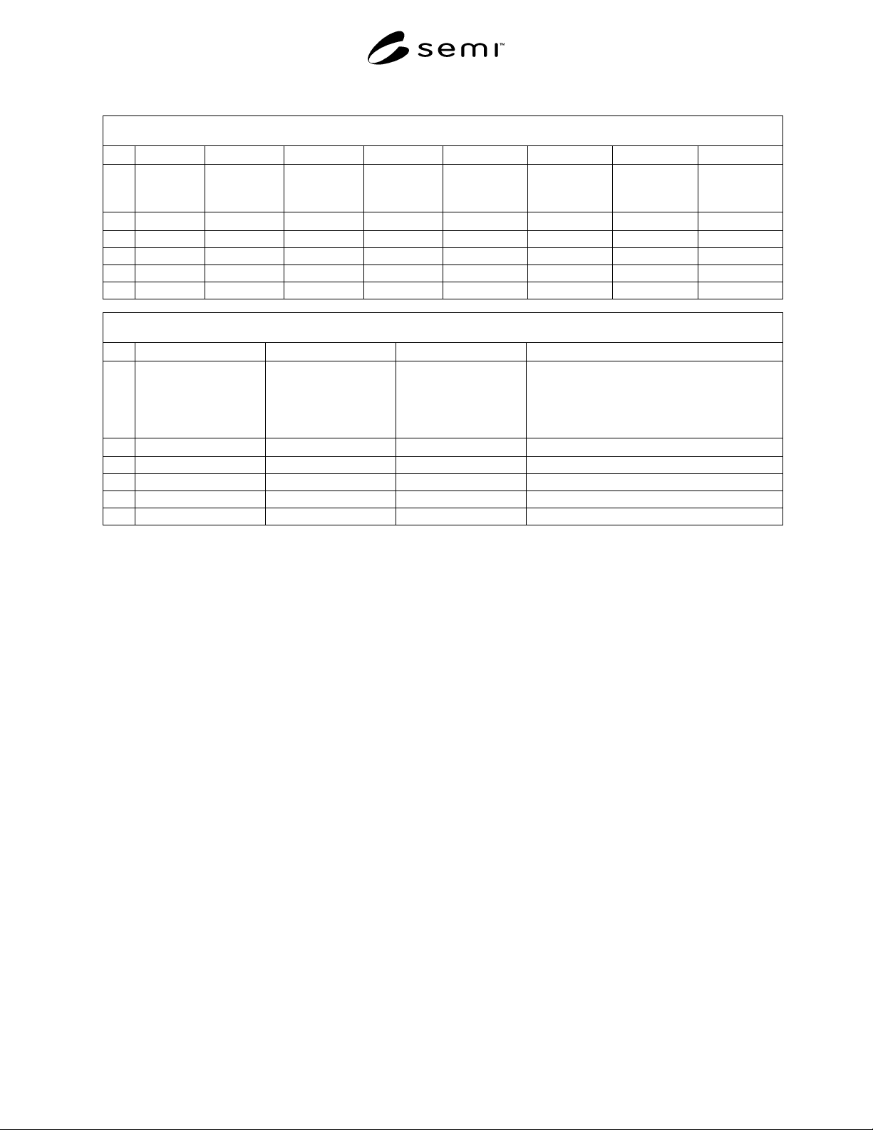
400 Electrical Power
AC AD AE AF AG AH AI AJ
1
Current
Maximum
Phase A
Current
Maximum
Phase B
Current
Maximum
Phase C
Current
Maximum
Neutral
Current THD
Phase A
Current THD
Phase B
Current THD
Phase C
Current THD
Neutral
2
amps amps amps amps % % % %
3
4
5
6
400 Electrical Power
AK AL AM AN
1
Process Cycle Energy Equipment Power
Characterization Plot
(Is power to this
connection included in
plot?)
Drawing References Electrical Power Comments
2
kWh yes or no text text
3
4
5
6
13 Water Data Sheet
13.1 Include in the Water Data Sheet the requested
information for equipment connections to facilities
systems including (but not limited to) deionized water,
ultrapure water (UPW), raw water, hot water, steam,
chilled water, and process cooling water systems.
13.2 Data Sheet 500, Water contains the following
items.
13.2.1 Equipment Component (500A) — Enter the
name of the equipment component where the
connection is located. The name should the same name
used in Data Sheet 200 and 300. For example:
Mainframe or Pump.
13.2.2 Water Connection Number (500B) — Enter a
unique connection number for every utility connection.
For example: 501, 502, 503, and so on. For loop
distribution utilities, the supply connection could be
502S and the corresponding return connection could be
502R. For loop distribution utilities, return connection
data should be entered in the row (in this data sheet)
immediately below the supply connection data row.
13.2.3 Connection Label on Equipment (500C) —
Enter the name found on the label that identifies this
physical connection on the equipment. For example
UPW Supply.
13.2.4 Utility Type (500D) — Enter the name of water
service to be provided through the connection. For
example: PCW, DI, Hot DI, or city water.
13.2.5 Line Source (500E) — Identify the source of the
supply line for this connection. If the line comes from a
provided component covered in the data sheets enter the
connection number(s) at the other end of the line. If the
line comes from a facilities source enter facilities
system. For example: 503 or facilities system.
13.2.6 Purity Requirements (500F) — List minimum
purity requirements and basis of purity. If applicable
indicate SEMI standards and filtration requirements.
13.2.7 Contaminants (500G) — Enter the type and
value of any significant impurities.
13.2.8 Minimum Pressure (500H) — Enter the
minimum supply pressure necessary for the equipment
to operate correctly.
13.2.9 Maximum Pressure (500I) — Enter the highest
supply pressure that can be used to operate the
equipment correctly.
13.2.10 Maximum Pressure Fluctuation (500J) —
Enter the maximum supply pressure change during the
processing cycle for the equipment to operate correctly.
The data entered for a loop distribution return
connection should be n/a (not applicable).