semi合集-English.pdf - 第4763页
SEMI C14-95 © SEMI 1995, 2002 3 7.4 Break-in Test — Identify the period of time required to obtain 3 consecu tive one hour sampling intervals without detection of particles and the total numb er of particles recorded dur…

SEMI C14-95 © SEMI 1995, 2002 2
system. Care should be taken to provide an adequate
exhaust length so that back diffusion of particles does
not affect the system background at 2 times the
sampling flow rate. This length will depend upon the
particle concentration in the ambient environment and
other factors.
6 Procedure
6.1 Static Background Test
6.1.1 This test applies to all apparatus described in this
document and should be performed prior to other tests.
6.1.2 Remove the filter cartridge from the filter
housing and replace the test filter in Figure 2 with the
empty housing.
6.1.3 Purge the system at 100 m
3
/hr (3530 standard
cubic feet per hour (scfh)). Measure particle
concentration for a minimum of 45 sample intervals,
each at least 6 standard liters (0.19 scf) or 4 minutes,
whichever is greater. Continue to purge the system until
45 consecutive sample intervals without a particle being
detected are recorded.
6.2 Dynamic Background Test
6.2.1 This test applies to the apparatus for pulse test as
shown in Figure 2 with the test filter replaced by an
empty filter housing.
6.2.2 Purge at a flow rate of 5 m
3
/hr (177 scfh) until 5
consecutive 60-second sample intervals without a
particle being detected are recorded.
6.2.3 Set the CNC sample interval time to 180 seconds.
Synchronize the start of this test with the start of a CNC
sample interval.
6.2.4 Purge at a flow rate of 5 m
3
/hr (177 scfh) for 190
seconds.
6.2.5 Instantaneously switch to a flow rate of 100 m
3
/hr
(3530 scfh) by turning ON the solenoid valve and purge
for 160 seconds.
6.2.6 Turn OFF the solenoid valve and purge at a flow
rate of 5 m
3
/hr (177 scfh) for 200 seconds.
6.2.7 Repeat Section 6.2.5 and Section 6.2.6 until 20
consecutive pulses without a particle being detected are
recorded.
6.3 Break-in Test
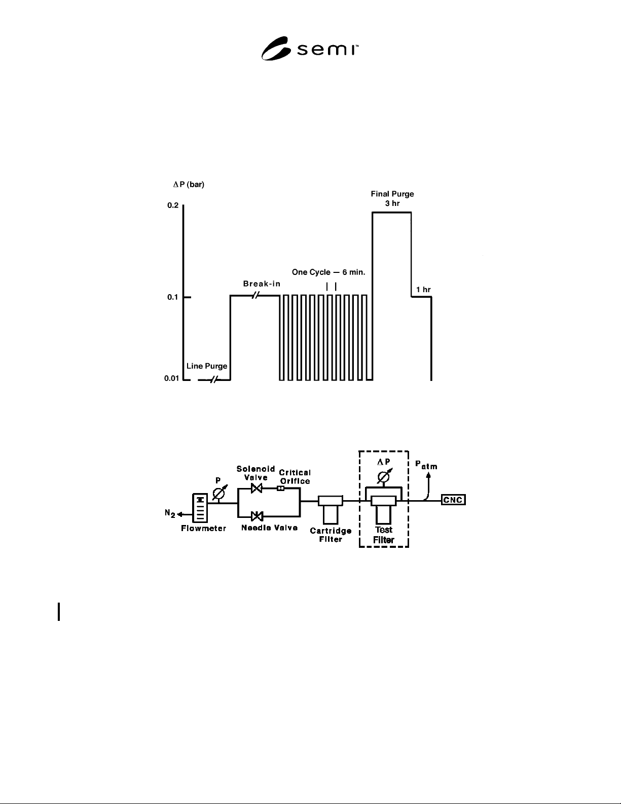
6.3.1 The test setup apparatus is shown in Figure 2.
Purge at a relatively low flow rate corresponding to a
∆p of 0.01 bar (0.15 psid) across the filter until 5
consecutive 60-second sample intervals without a
particle being detected are recorded.
6.3.2 Increase the purge flow rate so that the
corresponding ∆p is at least 0.1 bar and the flow rate is
at least 45 m
3
/hr (1590 scfh).
6.3.3 Record hourly particle concentration averages.
6.3.4 Stop the test when no particles are detected in 3
consecutive hourly sampling intervals.
6.4 Pulse Test
6.4.1 The apparatus is shown in Figure 2. Purge at a
relatively low flow rate corresponding to a ∆p of 0.01
bar across the filter until 5 consecutive 60-second
sample intervals without a particle being detected are
recorded.
6.4.2 Set the CNC sample interval to 180 seconds.
Synchronize the start of this test with the start of a CNC
sample interval.
6.4.3 Purge at a low flow rate corresponding to a ∆p of
0.01 bar across the filer for 190 seconds.
6.4.4 Instantaneously switch to a higher flow rate
corresponding to a ∆p of 0.1 bar (0.15 psid) across the
filter by turning ON the solenoid valve and purge for
160 seconds.
6.4.5 Turn OFF the solenoid valve and purge at a low
flow rate (∆p = 0.01 bar) of 200 seconds.
6.4.6 Repeat Section 6.4.4 and Section 6.4.5 (160 secs
ON and 200 secs OFF) for a series of 10 flow pulses.
6.5 Final Purge Test
6.5.1 Purge the filter at a ∆p of 0.2 bar (3 psid) or a
flow rate of 90 m
3
/hr (3180 scfh), whichever is greater,
for 3 hours. Record the particle concentration.
6.5.2 Decrease the flow so that ∆p = 0.1 bar (0.15 psid)
or the flow rate is 45 m
3
/hr (1590 scfh), whichever is
greater, and purge for 1 hour. Record the particle
concentration.
7 Reporting of Test Results
7.1 Raw data should be reported for each test in the
format of a table including the number of sample
intervals, the sampling volume of each interval, the
sampling time of each interval, and the total number of
particles registered in each interval. In addition, the
relevant parameters for each test described in Sections
7.2–7.6 should be identified.
7.2 Static Background Test — Identify the period of
time required to obtain 3 consecutive hourly sampling
intervals without a particle being detected.
7.3 Dynamic Background Test — Identify period of
time required to obtain 20 consecutive flow pulses
without a particle being detected.
SEMI C14-95 © SEMI 1995, 2002 3
7.4 Break-in Test — Identify the period of time required to obtain 3 consecutive one hour sampling intervals
without detection of particles and the total number of particles recorded during this period.
7.5 Pulse Test — Identify the number of pulses during which particles were detected and the total number of
particle counts.
7.6 Final Purge Test — Identify the average particle concentration at each pressure.
Figure 1
Schematic of a Standard Test Sequence for Evaluating 10-inch Filters
Figure 2
Schematic of the Line Purge Test Setup
NOTICE: SEMI makes no warranties or representations as to the suitability of the standards set forth herein for
any particular application. The determination of the suitability of the standard is solely the responsibility of the user.
Users are cautioned to refer to manufacturer’s instructions, product labels, product data sheets, and other relevant
literature respecting any materials mentioned herein. These standards are subject to change without notice.
The user’s attention is called to the possibility that compliance with this standard may require use of copyrighted
material or of an invention covered by patent rights. By publication of this standard, SEMI takes no position
respecting the validity of any patent rights or copyrights asserted in connection with any item mentioned in this
standard. Users of this standard are expressly advised that determination of any such patent rights or copyrights, and
the risk of infringement of such rights, are entirely their own responsibility.
Copyright by SEMI® (Semiconductor Equipment and Materials
International), 3081 Zanker Road, San Jose, CA 95134. Reproduction o
f
the contents in whole or in part is forbidden without express written
consent of SEMI.

SEMI C15-95 © SEMI 1995, 2002 1
SEMI C15-95 (Reapproved 1102)
TEST METHOD FOR ppm AND ppb HUMIDITY STANDARDS
This test method was technically approved by the Global Gases Committee and is the direct responsibility of
the North American Gases Committee. Current edition approved by the North American Regional Standards
Committee on July 21, 2002. Initially available at www.semi.org October 2002; to be published November
2002. Originally published in 1995.
1 Purpose
1.1 This test will determine whether or not the quantity
of moisture delivered by a gaseous moisture standard is
in agreement with that predicted for the standard on the
basis of physical principles. It is expected that this
method will be used to validate moisture standards
before they are first placed in use, when deviation from
expected performance is likely or suspected, and at
other times as seems necessary.
1.2 The test method assumes the existence of a reliable
moisture analyzer. Although extensive precautions are
described to ensure the validity of the analyzer, it is
always possible that the test could yield a faulty result
through some unforeseen defect in the analytical
equipment.
1.3 Given that moisture generation is subject to many
pitfalls, it will be required that the predicted moisture
concentration delivered by the standard and the
measurement of that level by the analyzer be
independent, and that they agree. The level of
agreement can vary depending on the degree of
precision claimed for the moisture standard, but in any
case the measured and predicted results should be
within 10% over the entire range of the moisture
standard. If not, then the validation should be repeated
after verifying the physical measurement upon which
the prediction is based and any other parameters
deemed suspect.
2 Scope
2.1 This method is intended to be applicable to any
type of gaseous standard delivering a quantity of
moisture in the ppm range or lower, provided the
delivered moisture concentration is predictable on the
basis of fundamental principles of physics. Thus, any
standards which rely solely on characterization by
analysis are specifically excluded.
2.2 As part of this test, a procedure is described for
qualifying certain moisture analyzers considered
suitable for use in qualifying moisture standards.
Moisture analyzers intended for other applications may
need to satisfy different criteria.
2.3 As the most accurate and reliable moisture
analyzers currently available operate primarily in the
ppm range, this test focuses on validation of moisture
standards in this range. The need for ppb moisture
standards is addressed by specifying procedures for
reducing the output of ppm moisture standards to the
ppb range.
2.4 This standard does not purport to address safety
issues, if any, associated with its use. It is the
responsibility of the users of this standard to establish
appropriate safety health practices and determine the
applicability or regulatory limitations prior to use.
3 Limitations
3.1 If no higher level of accuracy is specified by the
user, then a moisture standard shown to be valid by this
method will generate moisture levels which deviate
from the expected values by no more than 20%. The
method leaves open to the user the option of using
sound statistical methods to specify that a given
moisture standard will generate levels showing a closer
agreement with expected values.
3.2 Validation based on this test method is good for a
limited time. The acceptable interval between
validations depends on the nature of the standard and is
not addressed by this method. Thus any citation of
validation results should be accompanied by the date(s)
on which validation was performed.
4 Referenced Documents
This method is based upon principles outlined in F.
Mermoud, M.D. Brandt, and J.J.F. McAndrew, “Low
Level Moisture Generation,” Analytical Chemistry, 63
(2): 198-202 (1991).
5 Device under Test (Test Specimen)
5.1 Definition of a Moisture Standard — A moisture
“standard” is defined to be any device capable of
delivering a flow of humidified gas at controlled
pressure, with no input being provided by the user
except nitrogen of UHP grade (moisture < 1 ppm) or air
of equivalent purity. Any device, such as a permeation
tube, which can provide a predictable amount of
moisture but does not include a means to deliver gas to
and from it, will not be considered a moisture standard
by itself. A device which requires gas of higher purity
than UHP grade will include a purifier capable of
purifying UHP nitrogen to this level.