semi合集-English.pdf - 第4095页
SEMI F59-0302 © SEMI 2000, 2002 1 SEMI F59-0302 TEST METHOD FOR DETERM INA T ION OF FILTER OR GA S SYSTEM FLOW PRESSURE DROP CURVES This tes t method wa s technically approved by the Global Fac ilities Comm ittee and is …
SEMI F58-1000 © SEMI 2000 4
9 Reporting Results
9.1 Complete moisture response curves for all test
systems and relevant test blanks should be included. A
summary sheet may compare systems in terms of
“induction time,” peak height, and/or decay time
(detected moisture concentrations may be plotted as a
function of time for the test systems). Temperature,
pressure, and flow measurements, and as complete a
record as possible of all experimental variables should
be noted.
Regulator
3-port Valve
Pressure gauge/
Transducer
MFC
Dryer +
Filter
Moisture
Generator
APIMS
P1
Regulator
V2
V3
V4
V5
MFC
Test system
(At 30°C)
To vent
To vent
UHP N
2
Bypass loop
UHP N
2
V1
P2
To vent
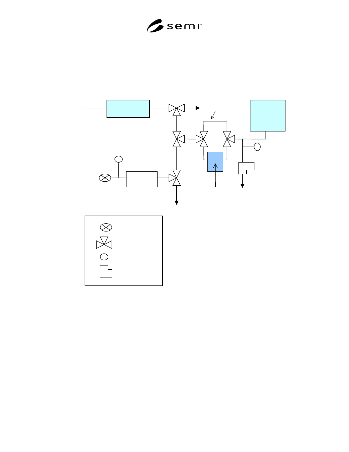
Figure 1
APIMS Moisture Test Schematic
NOTICE: SEMI makes no warranties or representations as to the suitability of the standards set forth herein for any
particular application. The determination of the suitability of the standard is solely the responsibility of the user.
Users are cautioned to refer to manufacturer’s instructions, product labels, product data sheets, and other relevant
literature with respect to any materials mentioned herein. These standards are subject to change without notice.
The user’s attention is called to the possibility that compliance with this standard may require use of copyrighted
material or of an invention covered by patent rights. By publication of this standard, SEMI takes no position
respecting the validity of any patent rights or copyrights asserted in connection with any item mentioned in this
standard. Users of this standard are expressly advised that determination of any such patent rights or copyrights and
the risk of infringement of such rights, are entirely their own responsibility.
Copyright by SEMI® (Semiconductor Equipment and Materials
International), 3081 Zanker Road, San Jose, CA 95134. Reproduction o
f
the contents in whole or in part is forbidden without express written
consent of SEMI.

SEMI F59-0302 © SEMI 2000, 2002 1
SEMI F59-0302
TEST METHOD FOR DETERMINATION OF FILTER OR GAS SYSTEM
FLOW PRESSURE DROP CURVES
This test method was technically approved by the Global Facilities Committee and is the direct responsibility
of the North American Facilities Committee. Current edition aproved by the North American Regional
Standards Committee on November 27, 2001. Initially available at www.semi.org December 2001; to be
published March 2002. Originally published October 2000.
NOTE: This document was entirely rewritten for
publication in 2002.
1 Purpose
1.1 The purpose of this document is to define a method
for testing filters or gas systems being considered for
installation into a high-purity gas distribution system or
on semiconductor manufacturing equipment,
respectively. Application of this test method is
expected to yield comparable data among filters or gas
systems.
1.2 This document establishes a test method for
preparing a pressure drop versus flow rate curves for
filters and gas systems.
2 Scope
2.1 This procedure applies to clean filters including
those cartridges of metal, ceramic and membrane
construction. The pressure drops for integral
housing/cartridge combination units are determined as a
single set of values. For housings with removable filter
cartridges, the flow curves of the housing and
housing/cartridge combination are determined
separately.
2.2 This procedure applies to high-purity gas systems.
This procedure applies to face-seal, surface mount—
modular, and monolithic integrated gas systems.
2.3 This standard does not purport to address safety
issues, if any, associated with its use. It is the
responsibility of the users of this standard to establish
appropriate and safety health practices and determine
the applicability of regulatory limitations prior to use.
3 Limitations
3.1 For separable filtration units, a single cartridge
pressure drop value cannot be combined to give the
pressure drop value for an extended length cartridge,
because of the limitations imposed by a common outlet
port for the assembly.
3.2 This method is written with the assumption that the
operator understands the use of the apparatus at a level
equivalent to six months of experience.
3.3 This method is written to test a filter under normal
operating conditions. It does not prescribe a procedure
for reverse flow testing since operation of the filter in
this manner is not recommended by the manufacturers.
3.4 Components that induce line pressure changes on a
system such as pressure regulators, and MFCs are not
considered in this test method.
3.5 Proper flow of low vapor pressure gases can be
effected by small pressure drops and may need to be
evaluated independently.
4 Referenced Standards
NOTE 1: As listed or revised, all documents cited shall be
the latest publications of adopted standards.
4.1 ASME Performance Test Code PTC 19.5, 1972
“Applications.” Part II of “Fluid Meters, Interim
Supplement on Instruments and Apparatus.”
1
5 Terminology
5.1 Abbreviations and Acronyms
5.1.1 CDA clean, dry air
5.1.2 °C degrees Celsius
5.1.3 DUT device under test
5.1.4 kg kilogram
5.1.5 kPa kilopascals, (kNm
-2
)
5.1.6 m meter
5.1.7 MFC mass flow controller
5.1.8 N Newton (kg m/s
2
)
5.1.9 P pressure in kiloPascal (kPa)
5.1.10 POC — point of connection
5.1.11 psi pounds per square inch
5.1.12 psia pounds per square inch absolute
5.1.13 psid pounds per square inch differential
5.1.14 psig pounds per square inch gauge
1 American Society of Mechanical Engineers (ASME) International,
3 Park Avenue, New York, NY 10016-5990

SEMI F59-0302 © SEMI 2000, 2002 2
5.1.15 s second
5.1.16 scfm standard cubic feet per minute
5.1.17 slpm standard liters per minute
5.1.18 T (K) temperature in Kelvin
5.1.19
∆
P differential pressure in kPa
5.1.20
∆
P(Housing) (kPa, differential) differential
pressure of housing in kiloPascal, differential
5.1.21
∆
P(Unit) (kPa, differential) differential
pressure of filtration unit in kiloPascal, differential
5.1.22
∆
P(cartridge) (kPa, differential) differential
pressure of cartridge element in kiloPascal, differential
5.2 Definitions
5.2.1 filter cartridge the filtration element.
5.2.2 filter housing the shell that contains the filter
cartridge.
5.2.3 filtration unit the assembly consisting of a
filter cartridge and housing.
5.2.4 gas box — a gas distribution subsystem which
generally contains the final shut-off valve(s) prior to the
POC.
5.2.5 gas pallet — individual gas distribution
subsystems within a gas box that control flow of gas to
individual process chambers.
5.2.6 gas stick — a series of components for an
individual gas within a gas box. It may contain valves,
a regulator, a pressure transducer, a purge line, an
MFC, and a filter.
5.2.7 integral unit the filter cartridge and housing
are not separable.
5.2.8 normal conditions 101.3 kPa (14.7 psia) and
ambient temperature conditions 293.15 K (20
o
C).
5.2.9 separable unit the filter cartridge and housing
can be disassembled.
5.2.10 spool flow through component — a null
component consisting of an electropolished flow
passage and appropriate fittings used in place of the test
component.
5.2.11 standard conditions 101.3 kPa, 273.15 K
(14.7 psia, 0
o
C).
6 Summary of Method
6.1 This test method describes the test equipment and
procedures for determining the flow pressure drop of
filters or gas systems. The differential pressure is
measured across a DUT at various inlet pressures and
flows. If the filtration unit is separable the individual
contributions from the housing and cartridge are
determined.
7 Interferences
7.1 Test stand must be of adequate dimensions so that
it does not limit the flow through the test DUT. The
pressure drop for the test stand must be insignificant
compared to the pressure drop for a DUT at the test
flow rate.
8 Apparatus
8.1 pressure regulator
8.2 downstream flow regulating valve
8.3 flow meter capable of measuring flow rates to
better than 5% full scale and of appropriate range.
8.4 several pressure transducers or gauges
8.5 differential pressure transducer (0.67 kPa, (0.1 psi)
sensitivity)
8.6 Test stand
8.7 Temperature measuring device (
o
C)
9 Reagents and Materials
9.1 Test Gas nitrogen or CDA filtered to < 0.02
micrometer with a dew point of less than or equal to –
40
o
C.
10 Safety Precautions
10.1 Safety Precautions This test method may
involve hazardous materials, operations, and
equipment. This test method does not purport to
address all of the safety problems associated with its
use. It is the responsibility of the user to establish
appropriate safety and health practices and to determine
the applicability of regulatory limitations prior to its
use.
10.2 The user must have a working knowledge of the
respective instrumentation, must practice proper
handling of test components, and must understand good
laboratory practices. The user should not operate the
components in such a manner as to exceed the ratings
(i.e., pressure, temperature, flow and voltage).
11 Test Specimen
11.1 A gas box may consist of several gas pallets that
uniquely control flow of gases to a specific process
chamber. More than one gas stick layout is possible on
the pallet. The user shall test only one stick at a time