semi合集-English.pdf - 第4496页
SEMI D19-0305 © SEMI 1999, 2005 3 8.2 This standa rd may involve hazardous materials, ope rations and equipment. This standard does not purport to address all of the safety problems associated with its use. It is the res…
SEMI D19-0305 © SEMI 1999, 2005 2
5.1.2 Definitions of additional terms used in this document may be found in JIS Z8113, JIS Z8122 and IEC
Publication 50 (845).
6 Summary of Method
6.1 A sample is placed in a suitable test container at controlled temperature for a specified period of time.
6.2 The sample is removed from the bath and residual chemicals removed.
6.3 The sample is examined visually for qualitative changes in appearance.
6.4 The sample is examined by microscope and/or surface profiler (stylus type) for material swelling.
6.5 The sample is measured per color layer for spectra transmittance.
6.6 The color difference for each color layer is calculated in one of two systems.
7 Apparatus
7.1 Test Container — A clean container shall be used with a sufficient size and depth to accommodate the sample
and appropriate chemicals. The container material must be chosen which will not be affected by tests executed under
this method. Note that chemicals should not change in quality by test container.
7.2 Instrumentation
7.2.1 Color Illuminator — This light source shall have chromaticity, color rendering, luminance and intensity
uniformity, diffusion, and a sufficient illumination area for observation of the samples to be measured.
7.2.2 Floodlight — This light shall have luminance uniformity and an illumination area sufficient for the samples to
be measured.
7.2.3 Microscope — The microscope used shall have appropriate magnification, normally 50
400.
7.2.4 Spectrophotometer — The spectrophotometer shall be in conformance with JIS Z8722 or an equivalent
standard.
7.2.5 Surface Profiler — The equipment which can measure the thickness with X-Y stage.
8 Reagents and Test Conditions
8.1 No specific requirements are described for the reagents. As long as the test conditions are reported with the test
result, any combination of chemical reagents with any condition can be used for the test. The test conditions should
reflect actual process conditions, which are specific for the selected FPD manufacturer. Some reagents suggested for
the test are given in Table 1.
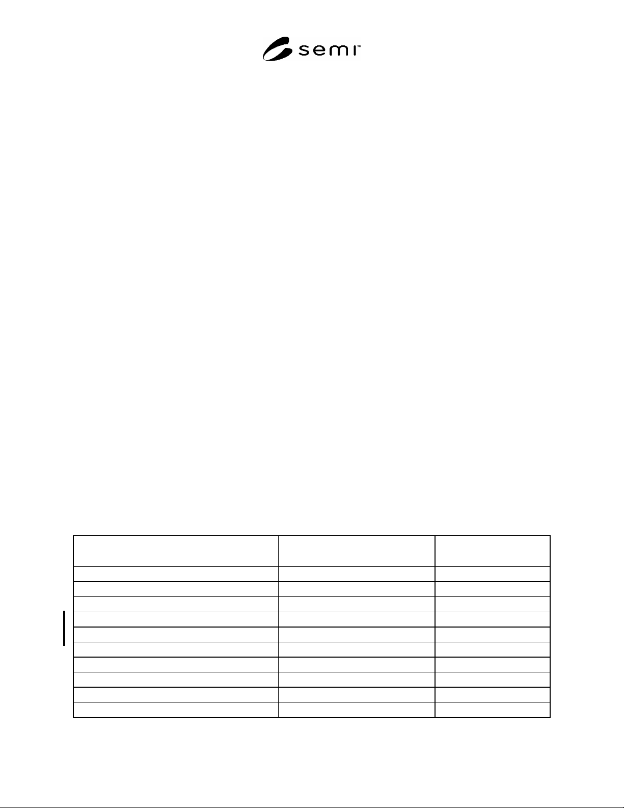
Table 1 Chemicals Used for Chemical Resistance Tests and Related Conditions
Chemical
#1
Liquid Temperature (
o
C)
Soak Time
(minutes)
N-methyl-2 pyrolidone (NMP)
23 2
30
-butyrolactone 23 2
30
2-propanol (IPA)
23 2
30
propylene glycol monomethyl ether Acetate
23 2
30
ethylene glycol monobutyl ether
23 2
30
2.38% tetramethyl-ammoniumhydroxide (TMAH)
23 2
30
18% HCl
23 2
30
18% HCl
40 5
10
5% NaOH
23 2
10
5% KOH
23 2
10
#1
% = % by weight
SEMI D19-0305 © SEMI 1999, 2005 3
8.2 This standard may involve hazardous materials, operations and equipment. This standard does not purport to
address all of the safety problems associated with its use. It is the responsibility of the user of this standard to
establish appropriate safety and health practices and determines the applicability of regulatory limitations prior to
use.
9 Samples
9.1 FPD color filters are used as samples. For HCl resistance tests, color filters without ITO should be used.
NOTE 1: The test report shall identify whether or not ITO is present on the sample.
10 Procedure
10.1 Pour the selected chemicals into a test container.
10.2 Adjust the temperature of the chemicals to a predetermined value.
10.3 Place the sample, film side up, into the chemicals and cover the test container to prevent chemical evaporation.
10.4 Leave the sample in the chemicals for a predetermined period of time.
10.5 Remove the sample from the chemical bath. Completely remove all chemicals remaining on the sample.
NOTE 2: For chemicals, temperature and soaking time, refer to §8, Reagents and Test Conditions.
10.6 Evaluate the sample condition according to the following criteria:
10.6.1 Change of Appearance — During each test, observe any change of appearance, e.g., wrinkles, cracks, change
of surface conditions due to swelling, film peeling, and discoloration. The sample is compared with untreated
sample. Various observation techniques can be employed, including the following which is included for reference
only:
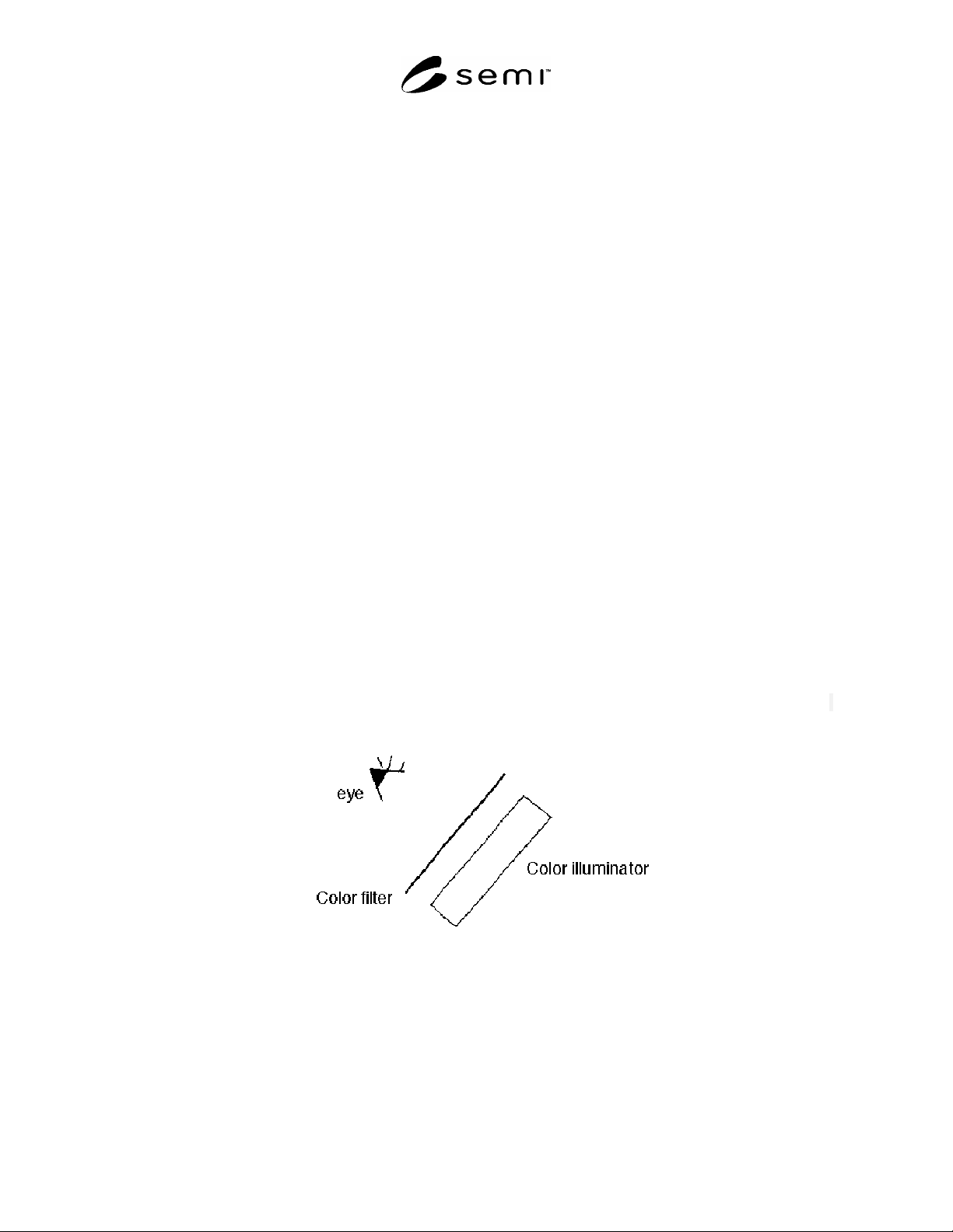
10.6.1.1 Visual observation of transmission of the color filter by use of a color illuminator (Figure 1).
10.6.1.2 Visual observation of reflectance of the film side of the color filter by use of a floodlight.
10.6.1.3 Microscope observation or transmission of a color filter by use of transmitted illumination.
10.6.1.4 Microscope observation of reflectance of the color filter by use of reflected illumination.
10.6.1.5 A surface profiler (stylus type) is used in order to measure the changes of film thickness of the color filter.
Figure 1
Visual Observation of Transmission of a Color Filter by Use of a Color Illuminator
10.6.2 Color Differences
10.6.2.1 Measure transmitted spectra of each colored layer of the color filter at any location. The center area of the
sample is recommended.
10.6.2.2 Calculate tri-stimulus values of each colored layer of the color filter in accordance with JIS Z8730.

SEMI D19-0305 © SEMI 1999, 2005 4
10.6.2.3 Repeat ¶¶10.6.2.1 and 10.6.2.2 on the same location of the sample.
10.6.2.4 Calculate color difference for each colored layer in the L*a*b* color system or the L*u*v* color
specification system from the tri-stimulus values measured before and after this test, according to the method
specified in JIS Z8730. Calculate either the difference E*ab or E*uv as the amount of color change of the color
filter.
NOTE 3: Both the L*a*b* and L*u*v* color specification system can be used to evaluate the color change.
11 Report
11.1 Report the following:
11.1.1 Report date
11.1.2 Test date
11.1.3 Ambient temperature, in
o
C
11.1.4 Conditions of the sample (construction of FPD color filter) – presence or absence of ITO film
11.1.5 Test conditions (name of chemicals, concentration, temperature and volume of chemicals, soaking time)
11.1.6 Observed changes in sample appearance between, before, and after the test.
11.1.7 The calculated color differences, for measurement location on each sample, and the color system used for
these calculations.
12 Precision and Accuracy
12.1 No test data currently exists on which to base these statements. Tests are planned to develop such data for both
single-laboratory repeatability and multi-laboratory reproducibility, on samples of the same nominal characteristics,
and across a range of nominal characteristics.
NOTICE: SEMI makes no warranties or representations as to the suitability of the standards set forth herein for any
particular application. The determination of the suitability of the standard is solely the responsibility of the user.
Users are cautioned to refer to manufacturer's instructions, product labels, product data sheets, and other relevant
literature, respecting any materials or equipment mentioned herein. These standards are subject to change without
notice.
By publication of this standard, Semiconductor Equipment and Materials International (SEMI) takes no position
respecting the validity of any patent rights or copyrights asserted in connection with any items mentioned in this
standard. Users of this standard are expressly advised that determination of any such patent rights or copyrights, and
the risk of infringement of such rights are entirely their own responsibility.
Copyright by SEMI® (Semiconductor Equipment and Materials
International), 3081 Zanker Road, San Jose, CA 95134. Reproduction of
the contents in whole or in part is forbidden without express written
consent of SEMI.