semi合集-English.pdf - 第598页
17 Related Documents 17.1 ANSI St andards 1 ANSI C39.5 Safety Requirements for Electrical and Electronic Measuring and C ontrolling Instrum en tation ANSI C42.100 Di ctionary of Electrical and Electronics Terms 17.2 …
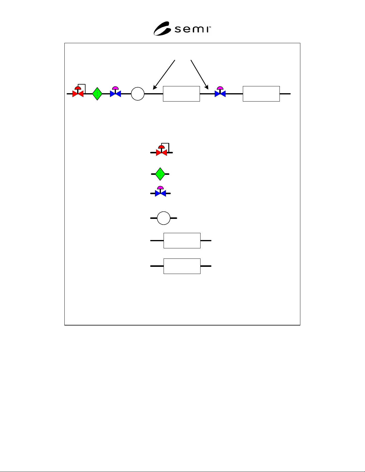
DUT
Flow
Standard
Flexible Gas Line
V1 V2R1 F1
P
P1
P
DUT
Flow
Standard
Regulator
Filter
Isolation Valve
Pressure Transducer
Device Under Test
Flow Standard
Figure 2
Test Setup
SEMI E80-0299 © SEMI 1999, 2004 7

17 Related Documents
17.1 ANSI Standards
1
ANSI C39.5 Safety Requirements for Electrical and
Electronic Measuring and Controlling Instrumentation
ANSI C42.100 Dictionary of Electrical and
Electronics Terms
17.2 ISA Standard
2
ISA S51.1 Process Instrumentation Terminology
17.3 ISO Standard
3
ISO 10012-1 Quality Assurance Requirements for
Measuring Equipment
NOTICE: SEMI makes no warranties or
representations as to the suitability of the standards set
forth herein for any particular application. The
determination of the suitability of the standard is solely
the responsibility of the user. Users are cautioned to
refer to manufacturer's instructions, product labels,
product data sheets, and other relevant literature,
respecting any materials or equipment mentioned
herein. These standards are subject to change without
notice.
By publication of this standard, Semiconductor
Equipment and Materials International (SEMI) takes no
position respecting the validity of any patent rights or
copyrights asserted in connection with any items
mentioned in this standard. Users of this standard are
expressly advised that determination of any such patent
rights or copyrights, and the risk of infringement of
such rights are entirely their own responsibility.
1
American National Standards Institute, Headquarters: 1819 L
Street, NW, Washington, DC 20036, USA. Telephone: 202.293.8020;
Fax: 202.293.9287, New York Office: 11 West 42nd Street, New
York, NY 10036, USA. Telephone: 212.642.4900; Fax:
212.398.0023, Website: www.ansi.org
2 The Instrumentation, Systems, and Automation Society, 67
Alexander Drive, PO Box 12277, Research Triangle Park, NC 27709,
Telephone: 919-549-8411, Fax: 919-549-8288, http://www.isa.org
3 International Organization for Standardization (ISO), 1, rue de
Varembé, Case postale 56, CH-1211 Geneva 20, Switzerland,
Telephone +41 22 749 01 11; Fax +41 22 733 34 30,
http://www.iso.org/
SEMI E80-0299 © SEMI 1999, 2004 8
Copyright by SEMI® (Semiconductor Equipment and Materials
International), 3081 Zanker Road, San Jose, CA 95134. Reproduction of
the contents in whole or in part is forbidden without express written
consent of SEMI.

SEMI E83-1000 © SEMI 1999, 20001
SEMI E83-1000
SPECIFICATION FOR 300 mm PGV MECHANICAL DOCKING FLANGE
This Provisional Specification was technically approved by the Global Physical Interfaces & Carriers
Committee and is the direct responsibility of the North American Physical Interfaces & Carriers Committee.
Current edition approved by the North American Regional Standards Committee on July 14, 2000. Initially
available at www.semi.org August 2000; to be published October 2000. Originally published June 1999.
1 Purpose
1.1 This specification is intended to promote
consistent interface features between Person Guided
Vehicles and SEMI E15.1 equipment.
2 Scope
2.1 This specification defines a mechanical standard
for the stationary (equipment) side of the docking
flange used by 300 mm Person Guided Vehicles
(PGVs). This flange is to be mounted to the floor within
the volume defined by SEMI E64 at SEMI E15.1 and
SEMI E64 compliant equipment.
2.2 This standard does not purport to address safety
issues, if any, associated with its use. It is the
responsibility of the users of this standard to establish
appropriate safety and health practices and determine
the applicability of regulatory limitations prior to use.
3 Limitations
3.1 This standard does not define the PGV (active)
side of the docking interface or carrier transfer. The
PGV and the PGV side of the docking interface designs
should comprehend the physical limitations of
equipment to which they are being applied.
4 Referenced Standards
4.1 SEMI Standards
SEMI E15 — Specification for Tool Load Port
SEMI E15.1 — Provisional Specification for 300 mm
Tool Load Port
SEMI E64 — Provisional Specification for 300mm
Cart to SEMI E15.1 Docking Interface Port
5 Terminology
5.1 Acronyms and Abbreviations
5.1.1 PGV — Person Guided Vehicle (cart)
5.2 Definitions
5.2.1 carrier — Any cassette, box, pod, or boat that
contains wafers (per SEMI E15).
5.2.2 cart — A floor based carrier transfer vehicle (per
SEMI E64).
5.2.3 docking — The act of locating a floor-based
carrier transport vehicle for carrier transfer to/from
equipment (per SEMI E64).
5.2.4 facial datum plane — A vertical plane that
bisects the wafers and that is parallel to the front side of
the carrier (where wafers are removed or inserted). On
tool load ports, it is also parallel to the load face plane
specified in SEMI E15 on the side of the tool where the
carrier is loaded and unloaded (per SEMI E57).
5.2.5 load face plane — The furthest physical vertical
boundary plane from carrier centroid on the side(s) of
the equipment where loading of the tool is intended (per
SEMI E15).
5.2.6 load port — The interface location on a tool
where carriers are placed to allow the tool to process
wafers (per SEMI E15).
5.2.7 transfer — To either load or unload (per SEMI
E15).
6 Requirements
6.1 The dimensions that define the universal docking
flange are listed in Table 1 and shown on Figure 1.
6.1.1 The minimum length of the docking flange is
defined by 2×w11. This minimum length is intended to
fit under the shadow of the smallest possible width
SEMI E15.1 compatible load port. The PGV and PGV
docking must provide full functionality given a
minimum length docking flange. No maximum length
has been specified.
6.1.2 One vertical pin (labeled VP in Figure 2) is
intended to be used for horizontal registration of the
PGV to the docking flange. This pin is also intended as
a feature for an active mechanism on the PGV to lock
on to.
6.2 There are three surfaces on the flange and a verti-
cal pin that can be used as the initial docking contacts
point(s) with the PGV. These have been identified as
surfaces A, B and C and pin VP as shown in Figure 2.
These features are the primary load bearing features
during the act of docking, no other features or surfaces
shall be used as initial docking contact points.