semi合集-English.pdf - 第1541页
SEMI E32-0997 © SEMI 1994 , 1997 36 Table A1-1 Ext e nded A tomic Transfer State Transiti on Table # Current St ate Trigger New State Action Comment 1 (Undef ined) Entry into P ORT M odel. INIT None. None. 2 INIT Port me…
SEMI E32-0997 © SEMI 1994, 199735
APPLICATION NOTES
A1-1 Transfer-Related Mechanisms — A transfer job
interacts very closely with port-related hardware. This
may include a variety of mechanisms such as port
doors, cassette indexers, robot arms, carrier restraints,
etc. The state models for the transfer job and atomic
transfers shown above relate to this port hardware, but
do not define hardware behavior directly. Therefore, an
additional state model is needed for the port hardware.
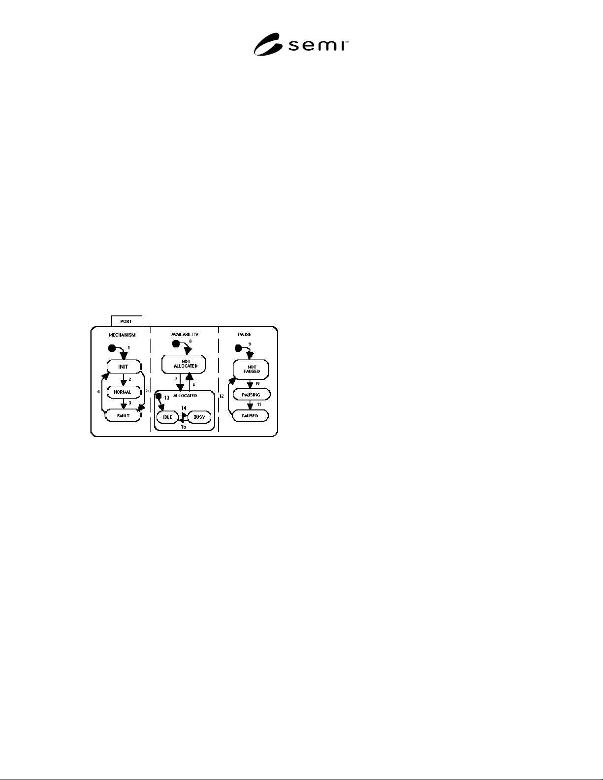
A1-1.1 Example Port State Model — Figure A1-1
provides an example of a state model for a port. It is
divided into three AND substates: MECHANISM,
AVAILABILITY, and PAUSE. These substates
represent the three most common areas of interest to the
host.
Below, the states shown in Figure A1-1 are described,
followed by a transition table. This is presented as an
example. The actual model is implementation-
dependent.
Figure A1-1
Example Port State Diagram
MECHANISM
This state pertains to the port's overall ability to
function. It has three substates: INIT, NORMAL, and
FAULT.
INIT
This is the default state upon powerup or reset of the
port. It includes some unspecified operations to ensure
that the port is ready to operate.
NORMAL
When in this substate, the port is in normal working
order.
FAULT
In this substate, a problem has been detected with a port
mechanism.
AVAILABILITY
This state pertains to the availability of the port to
perform a function. This state has two substates: NOT
ALLOCATED and ALLOCATED.
NOT ALLOCATED
In the NOT ALLOCATED state, neither the equipment
nor the host has allocated the port. The port is waiting
to be allocated to either a transfer job or to some
process-related task. This is the default state upon
equipment system startup.
ALLOCATED
In this state, the port is allocated to either the equipment
(typically process-related) or to the host for a transfer
job.
NOTE: If the port is allocated to an equipemnt function and
the host does not wish to wait for the equipment to release the
port, it must take some other action to force the port to
become available. One possibility is a “Pause for Transfer”
remote command that might be used during a processing
cycle.
IDLE
Port is allocated to a task (e.g., processing or transfer
job), but activity on the task has not yet begun.
PAUSE
This state pertains to the pausing of current port
activity. Pausing of the port is different than pausing a
transfer job which might be using the port.
NOT PAUSED
The port defaults to NOT PAUSED upon system
startup. In this state, port activities are not hindered by
the pause function.
PAUSING
In this state, the port has received a directive to pause
and is in the process of bringing the current activity to a
halt.
PAUSED
All port activity has ceased. The port is awaiting a
directive to resume activity.
Table A1-1 describes the transitions for the example
port state model. In the application-specific
implementation, events should be defined for all
significant occurences related to the model.

SEMI E32-0997 © SEMI 1994, 1997 36
Table A1-1 Extended Atomic Transfer State Transition Table
# Current State Trigger New State Action Comment
1 (Undefined) Entry into PORT Model. INIT None. None.
2 INIT Port mechanisms found to be functional. NORMAL None. None.
3 NORMAL A malfunction of the hardware occurs. FAULT None. None.
4 FAULT The malfunction is “fixed.” This may be a manual re-
initialization of the port.
INIT None. None.
5 INIT A problem occurs during initialization. FAULT None. None.
6 (Undefined) Entry into PORT Model. NOT ALLOCATED None. None.
7 NOT
ALLOCATED
The port is allocated to transfer or process job. ALLOCATED None. None.
8 ALLOCATED Port is released from current job. NOT ALLOCATED None. None.
9 (Undefined) Entry into PORT Model. NOT PAUSED None. None.
10 NOT PAUSED Directive issued to pause port. PAUSING None. None.
11 PAUSING Port activity has ceased. PAUSED None. None.
12 PAUSED Directive issued to resume activity. NOT PAUSED None. None.
13 (Undefined) Entry into ALLOCATED state. IDLE None. None.
14 IDLE Task activity begins. BUSY None. None.
15 BUSY Task activity ends. IDLE None. None.
A1-1.2 Additional Related Mechanisms — Many
equipment material ports have additional related
mechanisms that can aid or interfere with a transfer.
These mechanisms can be represented as parallel (or
orthogonal) states within the port state model. Most
such state models will be simple two–state instances
(e.g., open/closed, on/off).
In some circumstances, the host will have a need to be
able to understand the status of these mechanisms and
may wish to be informed of state changes. This is
especially true if the host is to do error handling and
preliminary diagnosis of problems. The host also may
need some level of remote commands to manipulate
these mechanisms. Some possible transfer-related
mechanisms are discussed below.
Port Material Sensors: These sensors detect the
presence or absence of material in a port. The change in
this status is important, and an event should be provided
to report change in this condition.
Port Doors: Some equipment closes the environment
internal to the equipment, except during material
transfer. The applicable states are normally
open/closed.
Port Elevator: Port elevators have multiple states such
as HOME, MOVING, SLOT 5 ACCESS, or interlocks
such as BLOCKED BY INTERNAL TRANSFER
ARM.
Robot Arm: The transfer arm may be in motion, may
be holding material, etc.
Carrier Restraints: On some ports, carriers are clamped
in place and cannot be removed unless the restraints are
released. There would be a clamped/unclamped state
model.
A1-2 WIP Tracking — WIP tracking refers to the
ability of an entity (host or equipment) to keep accurate
track of the material within its domain. Typically, the
equipment is expected to track the material's location
within its modules and subsystems, while the host may
take a more global view, knowing at which equipment
(or storage area) a specific transfer object resides.
The process of material movement crosses the
boundary of the equipment domain. Therefore, there
must be information exchanged between host and
equipment about what material is being transferred and
what the plans are for the material (e.g., when and how
processed).
It is outside the scope of this standard to define WIP
tracking capabilities, either at the host or equipment
level. However, it is critical for the material movement
function to supply enough information that WIP
tracking is feasible. Specifically, the material
movement messaging must identify the object being
transferred. WIP references are kept at a minimum. For
example, for a carrier containing wafers, the material
movement process would need to know the carrier
identifier, but need not be concerned with the specific
lot contained within. It is also outside the scope of this
standard to be concerned with the detailed contents or
status (e.g., processed or not) of a transfer object. These

SEMI E32-0997 © SEMI 1994, 199737
are important issues that should be dealt with
elsewhere.
A1-3 Error Handling — This section addresses some
common problems that may occur during the transfer
process. This is not intended to present hard and fast
rules for error handling, but rather to raise potential
issues and suggest possible solutions. Several primary
error or interrupt types are covered. For state model
representations of hardware faults, see Section A1-1.
NOTE: Transfer errors are not completely communicated
between transfer partners. The host may be responsible for
pausing or aborting (as needed) the activities of the partner or
equipment with an error condition.
A1-3.1 Macro Level Error Handling
1. Transfer Specification Error
This would consist of an error in the data contained in
the Transfer Job Create request. Some examples might
include specification of a static port as an active
transfer partner or the use of a non–existent port on the
equipment. Such an error should result in rejection of
the Transfer Job Create request.
2. Setup Error
It is during the setup for an atomic transfer that many
prerequisites are typically checked. A setup error may
be either a hardware or a transfer specification problem.
Hardware problems might be such events as cassette
elevator fault, door fails to open, etc. If a hardware
problem occurs, the transfer job is paused and the
hardware state model makes a transition to the FAULT
state (see Section A1-1). When the problem is
corrected, the host may resume the activity or stop the
transfer job.
A transfer specification problem would typically relate
to the presence or absence of material at specified
locations. If there is a transfer specification problem
found, a transition to the RESTORE state is made
(transition #5) and the transfer job is terminated.
3. Restore Error
A restore error occurs when the port cannot be brought
back to its desired physical condition for the NOT
ALLOCATED state. This would be a failure of a
hardware mechanism. The hardware should then
transition to the hardware FAULT state (see Section
A1-1). The “completeness” of the transfer job may not
be hindered by problems in the restore activities.
However, the next transfer job may be affected.
4. Transfer Error
Transfer errors may be of many types and of varying
levels of severity. Any error that occurs must be
reported to the host. If the error is caused by failure of a
port mechanism, a transition to the hardware FAULT
state should occur (see Section A1-1). The problem
might also stem from a problem with the transfer
specification or in the transfer recipe (i.e., specification
is legal, but does not match that of the partner). If
failure in the transfer hardware has occurred, the
transfer job should transition to the PAUSED state and
report it to the host. The host may choose to abort the
transfer job, or correct the problem and resume the
transfer job.
5. Timeouts
To ensure that all transfer problems are detected, the
host should implement a process for timeout monitoring
of transfer jobs. The timeout periods need only be very
rough estimates of the actual times required for the
transfer job (e.g., 2× or 3× actual). The host might
choose to monitor individual atomic transfers if tighter
tolerances are required. The goal is to ensure that
problems are not left undetected over extended periods.
To determine the proper time to allow for a transfer job,
the host would sum the estimated maximum times
needed for the individual atomic transfers which make
up the job
14
. The atomic transfer time estimates would
typically be determined by experience, since they rely
on the interactions of two different transfer partners. A
doubling or tripling of the average observed transfer
time would be a good estimate. In some cases, suppliers
of dedicated transfer equipment may be able to supply
reasonable estimates.
Transfer job timeout monitoring should begin with the
receipt of the “Transfer Job Started” message and end
with the “Transfer Job Complete” message (both via the
TRJobAlert service). If the host is monitoring the
atomic transfers, monitoring should begin at the
“Atomic Transfer Started” event and end at the
“Atomic Transfer Complete” event (both via the
TRJobEvent service). The host must ensure that
reporting of these events is enabled in this case.
If a transfer job exceeds the timeout period, the host
may either pause the transfer job or attempt to end it
with the stop command. The former may be preferred,
since human intervention is required in either case and
may enable a resume command to continue the transfer.
A1-3.2 Micro Level Error Handling
1. No Communication With Transfer Partner
If a transfer partner attempts to communicate with its
transfer partner and finds that the communications link
is not responding, it should inform the host via an event
14 This assumes that atomic transfers proceed sequentially. If they
may proceed in parallel, the sequence for each port may be summed
and the longest total chosen as the estimated time.