semi合集-English.pdf - 第6570页
SEMI G86-0303 © SEMI 2003 2 6.2.2 The radius of the s upports and t he loading edge shall be 0.3 mm ± 0.02 mm. 6.2.3 The width of supports B 1 and loadi ng edge B 2 shall be lo nger than t h e widt h of test speci men b.…

SEMI G86-0303 © SEMI 2003 1
SEMI G86-0303
TEST METHOD FOR MEASUREMENT OF CHIP (DIE) STRENGTH BY
MEAN OF 3-POINT BENDING
This test method was technically approved by the Global Assembly and Packaging Committee and is the
direct responsibility of the Japanese Packaging Committee. Current edition approved by the Japanese
Regional Standards Committee on January 10, 2003. Initially available at www.semi.org January 2003; to be
published March 2003.
1 Purpose
1.1 This test method defines a procedure for the
evaluation of die strength by the mean of 3-point
bending method.
2 Scope
2.1 This test method applies only for 3-point bending
method, and other methods will be defined by the
separate documents.
2.2 This test method is used to measure die strength for
dies from processed wafers.
2.3 Wafer thinning technology becomes popular to
meet the demand for thin packages, so the die strength
data is critical for the die quality and certification. This
standard is one of the documents, which describe the
Die Strength Evaluation Method, Measurement Data
Summary Technique and Data Usage for Test Report.
NOTICE: This standard does not purport to address
safety issues, if any, associated with its use. It is the
responsibility of the users of this standard to establish
appropriate safety and health practices and determine
the applicability of regulatory or other limitations prior
to use.
3 Referenced Standards
3.1 ISO Standards
1
ISO 468: Surface roughness — Parameters, their values
and general rules for specifying requirements
ISO/DIS 6508-1: Metallic materials — Rockwell
hardness test (scales A,B,C,D,E,F,G,H,K,N,T) — Part
1: Test method
NOTICE: Unless otherwise indicated, all documents
cited shall be the latest published versions.
1 International Organization for Standardization, ISO Central
Secretariat, 1, rue de Varembé, Case postale 56, CH-1211 Geneva 20,
Switzerland. Telephone: 41.22.749.01.11; Fax: 41.22.733.34.30
Website: http://www.iso.ch
4 Terminology
4.1 Definitions
4.1.1 deflection
δ
— distance over which the top or
bottom surface of the test specimen at midspan deviates
from its original position during flexure.
NOTE 1: It is expressed in millimeters (mm).
4.1.2 flexural stress
σ
f
— nominal stress of the outer
surface of the test specimen at midspan.
NOTE 2: It is calculated from the relationship given in
Section 8.1, equation (1) in Section 9.1, and is expressed in
megapascals (Mpa).
4.1.3 flexural stress at break
σ
fB
— flexural stress at
break of the test specimen.
NOTE 3: It is expressed in megapascals (Mpa).
4.1.4 loading edge — edge to apply the force to test
specimen.
4.1.5 speed of testing v — rate of loading edge
movement .
NOTE 4: It is expressed in millimeters per minute (mm/min).
4.1.6 supports — two supports to support the test
specimen during flexural test.
5 Summary of Method
5.1 This test method is based on 3-point bending test
and calculating the flexural stress at break.
6 Test Apparatus
6.1 Test Machine
6.1.1 The machine shall be capable of maintaining the
test speed with the tolerance of ± 0.05 mm/min.
6.1.2 The machine shall be capable of measuring and
recording the test force in newtons (N).
6.1.3 The error in the indicated force shall not exceed
1% of the actual value.
6.2 Supports and Loading Edge
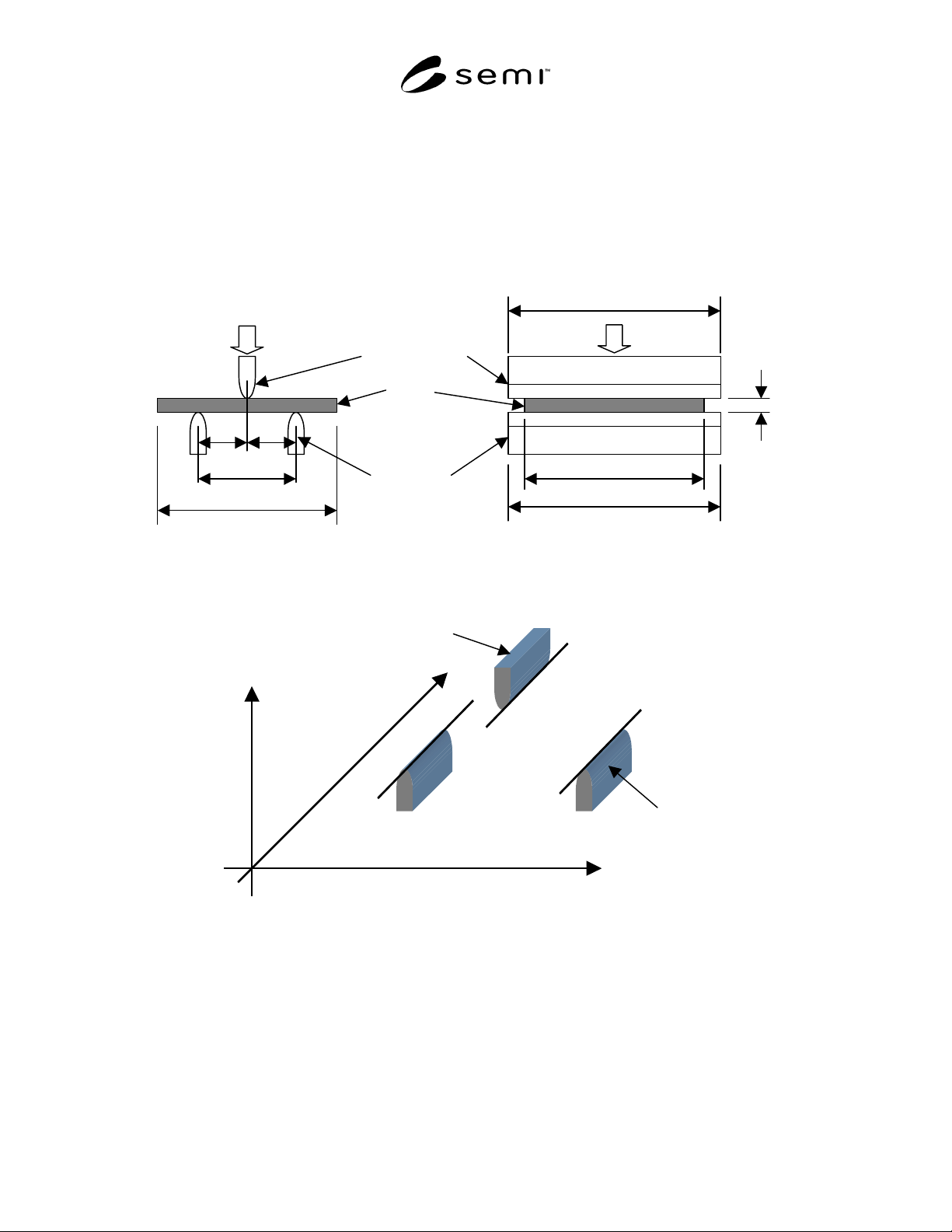
6.2.1 Two supports and a central loading edge shall be
arranged as shown in Figure 1.
SEMI G86-0303 © SEMI 2003 2
6.2.2 The radius of the supports and the loading edge
shall be 0.3 mm ± 0.02 mm.
6.2.3 The width of supports B
1
and loading edge B
2
shall be longer than the width of test specimen b.
6.2.4 Two supports shall be parallel to X direction
within ± 0.03 mm and to Z direction within ± 0.02 mm.
And two supports to the loading edge shall be parallel
to X direction within ± 0.03 mm and to Z direction
within ± 0.02 mm (see Figure 2).
6.2.5 The tip of the supports and loading edge shall be
hardened more than HRc60 specified in ISO/DIS 6508-
1.
6.2.6 The tip of the supports and loading edge shall
have the roughness less than 1.6 umRa specified in ISO
468.
Unit: mm
B
1
L
/2
L
/2
L
h
b
P
w
P
Loading edge
Supports
Test
specimen
B
2
Figure 1
Position of Test Specimen at Start of Test
Y
X
Loading edge
Support
Z
Figure 2
Arrangement of Supports and Loading Edge
SEMI G86-0303 © SEMI 2003 3
Datum plane Support
5 °
Figure 3
Setting Condition of Test Specimen
7 Test Specimens
7.1 The shape and dimensions of the test specimens
shall be agreed between the interested parties.
7.2 Test specimen shall be Silicon Die.
7.3 At least 25 test specimens shall be pulled from a
wafer.
8 Procedure
8.1 Measure the thickness h, width b, and length w.
The accuracy of h and b shall be within ± 5%.
8.2 Adjust the span L in accordance with the following
conditions,
at h < 0.1 mm : L ≤ 2 mm and L ≤ 50 h
at h ≥ 0.1 mm : 2 mm ≤ L and L ≤ 20 h
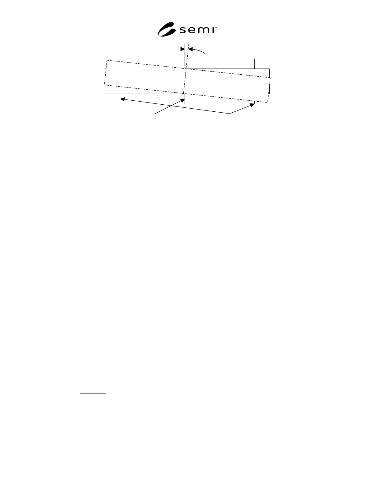
8.3 Place the test specimen on the two supports within
± 5° of the deviation from datum plane (see Figure 3).
The evaluated surface shall be applied the tensile force.
8.4 Set the test speed less than 5 mm/min in order to
avoid the impact on test specimen and apply the force at
midspan.
8.5 Record the force of the specimen at the break.
9 Calculation
9.1 Flexural Stress — Calculate the flexural stress
parameters defined in Section 4 using the following
equation:
(1)
σ
fB
=
3
P
B
L
2
bh
2
Where:
σ
fB
is the flexural stress at break in question (Mpa);
P
B
is the applied force at break, in newtons (N);
L is the span, in millimeters (mm);
b is the width, in millimeters (mm), of the test
specimen; and
h is the thickness, in millimeters (mm), of the test
specimen.
NOTE 5: Equation (1) can only be used for test specimens
with linear stress/strain behavior.
10 Test Report
10.1 The test report shall include the following
information:
• the directions major axes of the specimens if test
specimen has,
• the evaluated surface,
• the dimensions of the test specimens (thickness h,
width b, length w),
• the nominal span length used,
• the number of specimens tested,
• the speed of testing,
• the individual test results, the flexural stress at
break, and
• the date of the test.