semi合集-English.pdf - 第6834页
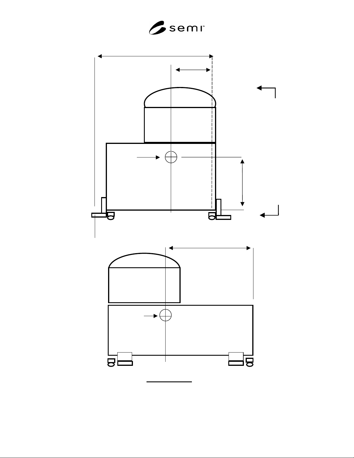
SEMI S2-0703a E © SEMI 1991, 2004 63 L1 L2 A h A A R L3 A B VIEW A – A F p(x) CG F p(y) Figure R5-1 Design Example

SEMI S2-0703a
E
© SEMI 1991, 2004 62
R5-2 Derivation of Section 19, Seismic Load Guidelines
R5-2.1 The horizontal loadings of 94% and 63%, found in Sections 19.2.1 and 19.2.2, were based on following
assumptions for factors in formula 32-2 in Section 1632.2 of the 1997 Uniform Building Code (UBC):
a
p
= 1.0 (i.e., treat the equipment as a rigid structure)
C
a
= 0.44(1.2) (i.e., seismic zone 4, soil profile type S
D
, and site 5 km from a seismic source type A)
I
p
= 1.0 and 1.5 for non-HPM and HPM equipment, respectively
h
x
/h
r
= 0.5 (i.e., equipment attached at point halfway between grade elevation and roof elevation)
R
p
= 1.5 (i.e., shallow anchor bolts).
Starting with equation 32-2, letting I
p
= 1.5, and substituting the above values:
F
p (ultimate)
= [(1.0 * 0.44(1.2) * 1.5)/ 1.5] [ 1 + 3(0.5)] W
p
= [0.44(1.2)] [ 1 + 1.5] W
p
= [0.528] [ 2.5] W
p
= [1.32] W
p
NOTE R5-2: This number is now adjusted from ultimate strength loading to yield strength loading by dividing by 1.4:
F
p (yield)
= F
p (ultimate)
/ 1.4
= [1.32] / 1.4 W
p
= [0.94] W
p
And for I
p
= 1.0,
F
p
(yield)
= [.94] [ 1.0/1.5] W
p
= [.63] W
p
Notes re selection of a
p
value of 1.0:
Table 16-O of 1997 UBC, line 3.C., was interpreted to read: “Any flexible equipment...”
in structural terms, the structure of typical semiconductor equipment is considered “rigid.”
R5-2.2 Assumptions Used for Above Derivation
R5-2.2.1 Because typical semiconductor equipment is considered rigid, a frequency response analysis was not
considered to be necessary.
R5-2.2.2 Seismic waves typically have vertical as well as horizontal components associated with them; however,
these components typically arrive out of phase (i.e., they do not reach maximum values simultaneously). The
vertical component serves to, in effect, reduce the amount of equipment mass that is available to resist overturning
or toppling. The task force chose to take this into account by limiting the calculated weight available to resist
overturning to 85% of the weight of the equipment. An alternate method, not chosen by the task force, could have
been to simultaneously apply a vertical (Z) force.
R5-3 Source for Examples of Seismic Anchorage Details
R5-3.1 Detailed illustrations of examples of seismic anchorage details were developed by Working Group #9 of the
Japan 300 mm (“J300”) effort, and were printed in their Report No. 9 in the 2nd Lecture, ICs Factory Design for
300 mm Wafer Line Standardizing Study, December, 1996.
SEMI S2-0703a
E
© SEMI 1991, 2004 63
L1
L2
A
h
A
A
R
L3
A B
VIEW A – A
F
p(x)
CG
F
p(y)
Figure R5-1
Design Example

SEMI S2-0703a
E
© SEMI 1991, 2004 64
DESIGN EXAMPLE (continued; refer to Figure R5-1 for illustration of example)
Disclaimer: the calculations below are not a complete seismic analysis. A complete analysis might also include such
things as: stress distribution through a multiple-fastener connection; prying action; bearing stress; simultaneous
combined stresses on the fasteners; and a review of weld geometry. A complete seismic analysis should be done by
a qualified engineer.
R5-4 Calculation of Lateral Force
R5-4.1 Lateral force on each leg is equal to F
P
/# of legs = F
P
/4
R5-4.2 The lateral force acts as shear on the floor anchor fasteners and shear or tensile loading on the equipment
anchor fasteners depending upon orientation. The actual reactions of the fasteners should be calculated by a
qualified engineer.
R5-5 Calculation of Overturning Force
R5-5.1 Sum the moments of the reactions on the system about line through the legs A and B:
(CW =+) M
AB
= 0 = F
P
(h) – 0.85W
P
(L
2
) –2R(L
1
)= 0
F
P
(h) – 0.85W
P
(L
2
)
R = _________________
2L
1
F
P
= 0.94W
P
W
P
(0.94h – 0.85L
2
)
R = _________________
2L
1
If 0.94h
0.85L
2
, then there is a tension reaction, R, at the two anchors, to resist overturning of system.
Example:
L1 = 50 inch
L2 = 20 inch
h= 36
W = 5000 lbs
Lateral force
= Fp/4 = 0.94(5000)/4 = 1175
W
P
(0.94h – 0.85L
2
)
Overturning force
= R =_________________
2L
1
= 5000 (0.94(36) – 0.85(20))
_____________________
2(50)
R = 842 lbs