semi合集-English.pdf - 第1046页
SEMI E4-0699 © SE MI 1980, 1999 8 6.8.1 Distinction — T he syst em byt e s o f a prim ary message m ust be dist inct from those of all currently open transactions initiated from the sa m e end of the communi cations link…
SEMI E4-0699 © SEMI 1980, 19997
6 Header Structure
6.1 The operation of all communications functions
above the block transfer protocol is linked to
information contained in a 10-byte data element called
the header. The header is always the first 10 bytes of
every block sent by the block transfer protocol. The
information in the header is also used by the message
protocol (see Section 7). The fixed format of the header
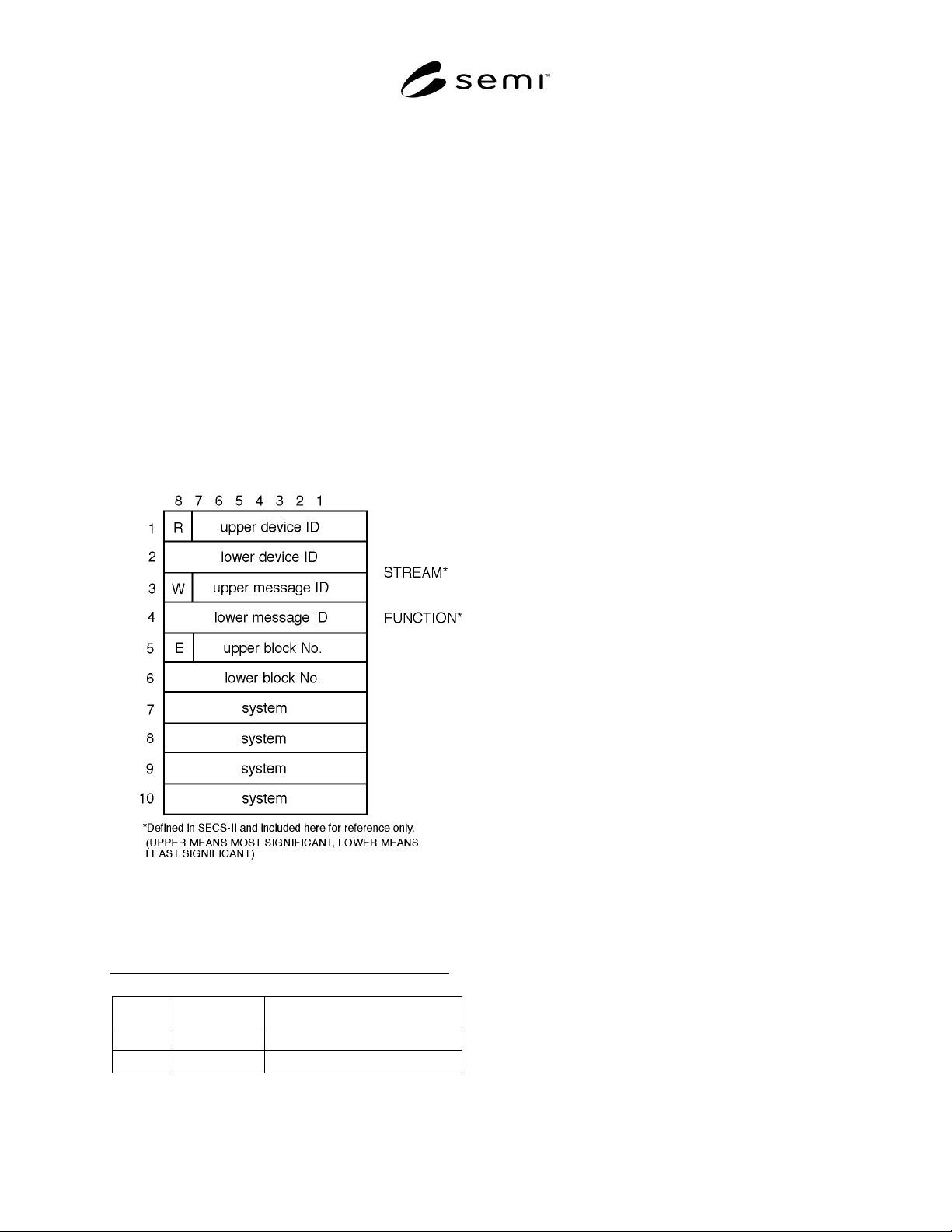
is described in this section. The general header structure
is shown in Figure 3.
NOTE: The header also contains information required by
SECS-II.
6.2 Reverse Bit (R-Bit) — The reverse bit (R-bit)
signifies the direction of a message. The R-bit is set to 0
for messages to the equipment and set to 1 for messages
to the host. The R-bit is included in the header so that
the direction of the message is contained in every block.
Figure 3
Block Header Structure
Table 3 Influence of the R-BIT
R-Bit Device ID Message Direction
0 Destination Host to Equipment
1 Source Equipment to Host
6.3 Device ID — The device ID defines the source or
destination of the message depending upon the value of
the R-bit as shown in Table 3. Device identification is a
property of the equipment and must be settable
according to Section 8. The host can view the device ID
as a logical identifier connected with a physical device
within the equipment. The host has no device ID.
6.4 Wait Bit (W-Bit) — The wait bit (W-bit) is used to
indicate that the sender of a primary message expects a
reply. A value of one in the W-bit means that a reply is
expected. A value of zero in the W-bit means that no
reply is expected. The W-bit must be set to zero in all
secondary messages. For multi-block messages, the
sender must ensure that the W-bit is the same in every
block of the message.
6.5 Message ID — The message ID identifies the
format and content of the message being sent (the
particular message is one of many possible for the
device in question). The exact message content is
equipment-dependent. The upper message ID is the
most significant portion of the ID.
6.5.1 Primary Message — A primar y message is
defined as any odd numbered message. An odd
numbered message will have bit 1 of the lower message
ID set to 1.
6.5.2 Secondary Message — A secondary message is
defined as any even numbered message. An even-
numbered message will have bit 1 of the lower message
ID set to 0.
NOTE: In SECS-II, byte three of the header (excluding the
W-bit) is known as the stream, and byte four of the header is
known as the function. See SECS-II for more information.
6.6 End Bit (E-Bit) — The end bit (E-bit) is used to
determine if a block is the last block of a message. A
value of one in the E-bit means that the block is the last
block. A value of zero means that more blocks are to
follow.
6.7 Block Number — A message sent as more than
one block is called a multi-block message. The first
block is given a block number of one, and the block
number is incremented by one for each subsequent
block until the entire message is sent. The blocks of a
multi-block message are sent in order. In a single-block
message, the block number must have a value of zero or
one. The maximum block number is 32,767. The upper
block number is the most significant portion of the
block number. (See also 7.2.)
6.8 System Bytes — The system bytes in the header of
each message for a given device ID must satisfy the
following requirements. (For a further discussion of
system bytes, see Related Information R1-5.)

SEMI E4-0699 © SEMI 1980, 1999 8
6.8.1 Distinction — The system bytes of a primary
message must be distinct from those of all currently
open transactions initiated from the same end of the
communications link. They must also be distinct from
those of the most recently completed transaction. (See
Section 7.3.) They must also be distinct from any
system bytes of blocks that were not successfully sent
since the last successful block send.
6.8.2 Reply Message — The system bytes of the reply
message are required to be the same as the system bytes
of the corresponding primary message.
6.8.3 Multi-Block Messages — The system bytes of all
blocks of a multi-block message must be the same.
7 Message Protocol
7.1 A message is a complete unit of communication in
one direction. The message protocol uses the services
of the block transfer protocol to send and receive
messages. The message consists of the message data
together with the following information from the header
— R-bit, device ID, W-bit, message ID, and system
bytes.
7.2 Message Send — When a message is ready to be
sent, the message send protocol performs the functions
described below. A block send failure terminates the
message protocol action on that message.
7.2.1 Message Length — The maximum data length in
a single block of a message is 244 bytes. The maximum
number of blocks that can be sent in a multi-block
message is 32,767, and so the maximum data length
allowed in one message is 244 × 32,767 bytes.
7.2.2 Message Blocking — Message blocking is the
division of the message data into blocks to be sent to
the Block Transfer Protocol. For best performance, it is
recommended, but not required, that the sender fill all
blocks of a multi-block message, except possibly the
last block, with the maximum 254 bytes. The receiver
of a multi-block message should be able to accept any
block size from 11 to 254 bytes, and should not require
consecutive blocks necessarily to be the same size.
7.2.2.1 Certain older implementations may impose
application-specific requirements on block sizes for
certain incoming messages. Beginning with the 1988
revision of the standard, new applications may not
impose application-specific requirements on incoming
block sizes. Applications implemented before 1988
may impose such requirements.
NOTE: In SECS-II, certain messages are defined as single-
block messages and must be sent as a single block in SECS-I.
7.2.3 Header — The message protocol must establish
the header in each block of the message according to
the requirements of Section 6.
7.2.4 Interleaving Messages — This standard allows,
but does not require, the support of more than one
concurrent open transaction. This standard allows, but
does not require, the support of interleaving the blocks
of different multi-block messages. (See documentation
requirements in 9.)
7.3 Transactions — A transaction is a primary
message and an optional corresponding secondary
message is called the reply. A transaction is opened
when a primary message is ready to be sent. A
transaction is closed when the last block of a primary
message requesting no reply has been sent, or when the
last block of the reply has been received.
7.3.1 Reply Linking — When a reply is expected for a
primary message, the message protocol starts the reply
timer for the transaction after the last block of the
message is successfully sent. When a primary message
is sent for which a reply is requested, an expected block
is established for the message receive algorithm. (See
Section 7.4.) The expected block will have the
complement of the R-bit, will have the same device ID,
will be the first block of a secondary message, and will
have the same system bytes as those of the given
primary message.
NOTE: In SECS-II, the reply will have the same upper
message ID (stream), and the lower message ID (function)
will either be one greater than that of the corresponding
primary message, or it will be zero.
7.3.2 Reply Timeout, T3 — The reply timeout, T3, is a
limit on the length of time that the message protocol is
willing to wait after the last block of a primary message
has been sent and before the arrival of the first block of
the reply. If the first block of the reply does not arrive
within the T3 limit, the expected block is removed from
the list of expected blocks, and the transaction is
aborted. A timer, called the reply timer, is used to
measure the time between the last block of the primary
message and the first block of its reply. Each open
transaction for which a reply is expected requires a
separate reply timer.
7.4 Message Receive — Each block successfully
received by the block transfer protocol is passed to the
message protocol. It is the task of the message protocol
to identify the blocks and assemble them into the proper
message.
7.4.1 Routing Error — When a piece of equipment
receives a block of data which has a device ID in the
block header which does not match its own device ID
and it has no other knowledge of this device ID, it can
assume that the block was sent in error.

SEMI E4-0699 © SEMI 1980, 19999
7.4.2 Duplicate Block Detection — A duplicate block
is a block which is exactly the same as the previous
block received by the Block Transfer Protocol. This
may occur when the receiver has sent an ACK but, for
some reason, the ACK did not arrive in time at the
sender, causing a send retry. A duplicate block is
detected by the SECS-I message protocol by comparing
the full 10-byte header of a block currently received by
the block transfer protocol with the header of the last
block accepted as non-duplicate by the message
protocol. If the headers are identical, the new block is a
duplicate and should be discarded. If the headers are
different, the new block is a non-duplicate. The header
of the non-duplicate block saved for comparison with
the next block passed on by the block transfer protocol,
and the block containing the header is further processed
by the message receive algorithm.
NOTE: Some implementations which follow the 1980 version
of SECS-I may not provide the unique headers required for
duplicate block detection. An option for disabling the
duplicate block detection is required to be compatible with
these systems.
7.4.3 Inter-Block Timeout T4 — The time interval
between the successful receipt of a block in a
multiblock message, and the successful receipt of the
subsequent block of the same message, is limited to
time T4. If this time is exceeded, the message is
cancelled and the transaction is aborted. A time called
the inter-block timer is used to measure the time
between block arrivals in the message protocol. There
must be one inter-block timer for each open multi-block
message currently being received by the protocol. As
each successive block of a message is received, the
corresponding inter-block timer is reset.
7.4.4 Algorithm — When a block arrives at the
message protocol, a combination of all the bytes in the
header is used to determine what to do with the block.
The operation of the message receive algorithm is to be
understood by following the logic flow in Figure 4. The
flow chart shown in Figure 4 and the description of the
algorithm below are not meant to imply that particular
implementation is required under this standard.
However, any SECS-I message protocol
implementation must include all the logic shown in
Figure 4 on page 11.
7.4.4.1 The description of the message protocol uses
the concepts of an expected block. When a (properly
routed and non-duplicate) block is received by the
message protocol, the first determination is whether the
block is one of the expected blocks or not. In order to
determine if a block is one of the expected blocks, the
header information is compared with the header
information in a list of expected blocks.
7.4.4.2 If the block is not one of the expected blocks,
it must be the first block of a primary message,
otherwise the block has been sent in error and can be
discarded. If the block is the first block of a primary
message, and it is not the last block of the message (E-
bit = 0), an inter-block timer for the given message is
established and set, and the expected block for the
given message is set to have the same R-bit, device ID,
system bytes, W-bit, message ID, and a block number
one greater than that of the block just received.
7.4.4.3 If the block is one of the expected blocks, then
it is either the first block of a reply message or it is part
of an open message.
7.4.4.4 If the block is the first block of a reply
message, the reply timer for the given message is
cancelled. For the first block of a reply message, the
expected block will have block number one (or possibly
zero if the reply is a single block message) and will be a
secondary message, but the full message ID is
undetermined. (See Section 7.3.1.)
7.4.4.5 If the block is the last block of the given
message (E-bit = 1), the message is complete. If the
message is a primary message for which a reply is
requested (W-bit = 1), the system bytes are saved for
sending with the reply message. (See Section 7.2.3.)
7.4.4.6 If the block is not the last block of the message
(E-bit = 0), then the inter-block timer for the given
message is reset, and the (next) expected block for the
given message is set to have the same R-bit, device ID,
system bytes, W-bit, message ID, and a block number
one greater than that of the block just received.
8 Parameter Setting
8.1 The eight protocol parameters are listed in Table 4.
The selection of baud rate should be based on system
performance. The value of the device ID is determined
by the particular system requirements and is generally
unique within one factory. The values of the next five
parameters are determined by the performance
characteristics of the host system and the baud rate of
the communication channel. The first seven parameters
must be adjustable by the user. All parameters must be
stored in such a manner that the settings will be retained
if the power fails or if the system software is reloaded.
The range and resolution of protocol parameters must
be at least as shown in Table 4. The M/S parameter is
set to master in the equipment and to slave in the host.