semi合集-English.pdf - 第3912页
SEMI F32-0998 © SEMI 1998 1 SEMI F32-0998 TEST METHOD FOR DETERMINATION OF FLOW COEFFICIENT FOR HIGH PURITY SHUTOFF V ALVES 1 Purpose 1.1 Thi s test meth od describes h ow t o determine two criteria us ed in s electing v…

SEMI F31-0698 © SEMI 19985
9.2.4 data management
9.2.5 reliability parameters, including lead detection
9.2.6 chemical usage
9.2.7 display of dispense systems
9.2.8 communication gateway to the factory alarm
system
9.2.9 on-line documentation
9.2.10 predictive maintenance planning
9.2.11 chemical interruptions to the fab by location,
indicating location of fault.
9.3 Maintenance — Maintenance of the BCD Systems
includes routine and preventative maintenance of
pumps, filters, valves, and other components.
9.4 Monitoring Programs — Each BCD System
should be monitored to determine if liquid chemicals
delivered to the tools for use in the manufacturing
process continually meet specifications and are within
initial and ongoing established process control limits.
9.4.1 Monitoring programs may include periodic
testing of the liquid chemicals to determine levels of
particles, trace metals assay, and other parameters of
interest. Certain tests may be done continuously on-line
(e.g., particles), and other analytical tests are performed
periodically from samples taken at various points in the
system.
NOTICE: These standards do not purport to address
safety issues, if any, associated with their use. It is the
responsibility of the user of these standards to establish
appropriate safety and health practices and determine
the applicability of regulatory limitations prior to use.
SEMI makes no warranties or representations as to the
suitability of the standards set forth herein for any
particular application. The determination of the
suitability of the standard is solely the responsibility of
the user. Users are cautioned to refer to manufacturer’s
instructions, product labels, product data sheets, and
other relevant literature respecting any materials
mentioned herein. These standards are subject to
change without notice.
The user’s attention is called to the possibility that
compliance with this standard may require use of
copyrighted material or of an invention covered by
patent rights. By publication of this standard, SEMI
takes no position respecting the validity of any patent
rights or copyrights asserted in connection with any
item mentioned in this standard. Users of this standard
are expressly advised that determination of any such
patent rights or copyrights, and the risk of infringement
of such rights, are entirely their own responsibility.
Copyright by SEMI® (Semiconductor Equipment and Materials
International), 3081 Zanker Road, San Jose, CA 95134. Reproduction o
f
the contents in whole or in part is forbidden without express written
consent of SEMI.

SEMI F32-0998 © SEMI 19981
SEMI F32-0998
TEST METHOD FOR DETERMINATION OF FLOW COEFFICIENT FOR
HIGH PURITY SHUTOFF VALVES
1 Purpose
1.1 This test method describes how to determine two
criteria used in selecting valves of appropriate size for
gases and liquids.
1.2 Methods and equations are spe cified and/or
referenced to assist in accurate calculation of pressure
drops across valves tested by this method.
2 Scope
2.1 This method establishes the te sting criteria for
determination of two coefficients specified in
ANSI/ISA-S75.02:
• Valve flow coefficient (C
v
)
• Critical pressure drop ratio factor (x
T
)
2.2 This method is to be used with ANSI/ISA-S75.02.
This method applies to manual and actuated valves for
use in both gas and liquid distribution systems used in
semiconductor manufacturing facilities. It is a test
method, where existing test methods are referenced and
limitations are imposed on test conditions. Specific
equations for calculating flow coefficients, choked flow
parameters, and pressure drops are referenced to the
appropriate ISA section.
3 Limitations
3.1 This method will limit the use and interpretation of
ANSI/ISA-S75.02 for use by manufacturers and users
of valves designed for the semiconductor industry.
3.2 This method is not intended to be used to
determine flow coefficients for valves used in vacuum
service.
4 Referenced Documents
NOTE: As listed or revised, all documents cited shall be the
latest publications of adopted standards.
4.1 ANSI Documents
1
ANSI/API 2530 — Part 2: Natural Gas Fluids
Measurement - Concentric, Square-Edged Orifice Met
ANSI/ISA-S-75.01 — Flow Equations for Sizing
Control Valves
1 American National Standards Institute, 11 West 42nd St., New
York, NY 10036, Telephone: 212.642.4900, Fax: 212.398.0023
ANSI/ISA-S75.02 — Control Valve Capacity Test
Procedure
5 Terminology
5.1 Acronyms
5.1.1 ∆P — Pressure drop across va lve, kPa (psi).
5.1.2 F
k
— Ratio of specific heats factor, where:
F
k
=
k
1.40
5.1.3 F
L
— Liquid pressure recovery factor
F
L
=
Q
max
m
3
nr
0.0865 *
C
v
*
P
1
kPa
−
0.96*
P
v
kPa
S
f
F
L
=
Q
max
g
pm
1.00 *
C
v
*
P
1
p
sia
−
0.96*
P
v
p
sia
S
f
ℜ
ℜ
ℜ
ℜ
ℜ
ℜ
ℜ
ℜ
ℜ
ℜ
5.1.4 gpm — Gallons per minute
5.1.5 k — Specific heat ratio
5.1.6 P
1
— Absolute pressure at upstream pressure
tap, kPa (psi).
5.1.7 P
2
— Absolute pressure at downstream pressure
tap, kPa (psi).
5.1.8 P
v
— Absolute vapor pressure of liquid at inlet
temperature, kPa (psi).
5.1.9 psia — Pounds per square inch absolute
5.1.10 psid — Pounds per square inch differential
5.1.11 Q — Volumetric flow rate
5.1.12 Q
max
— Maximum flow rate (c hoked flow
conditions) at a given upstream condition.
5.1.13 scfh — Standard cubic feet per hour
5.1.14 S
f
— Specific gravity of a liqu id relative to
water.
5.1.15 S
g
— Specific gravity of a gas relative to air.
5.1.16 T — Absolute temperature of t est gas or liquid,
°K (°R).
SEMI F32-0998 © SEMI 1998 2
5.1.17 x — Ratio of pressure drop to absolute inlet
pressure, dimensionless, where:
x =
∆P
kPa
P
1
kPa
x =
∆P
psid
P
1
psia
ℜ
ℜ
ℜ
ℜ
ℜ
ℜ
5.1.18 x
T
— Ratio of pressure drop to absolute inlet
pressure (
∆
p/p
1
) at choked flow condition,
dimensionless.
5.1.19 Y — Expansion factor for compressible fluids,
where:
Y =1 −
x
3 × F
k
× x
T
5.2 Definitions
5.2.1 flow coefficient C
v
— A numer ic constant used
to characterize the flow capacity of a valve.
5.2.2 vapor pressure condensation point — Pressure
at which fluid phase changes from liquid to gas, for a
given upstream condition.
5.2.3 vena contracta — Point in a duct where the
diameter of the fluid stream is smaller than the diameter
of the duct.
6 Test Fluids
6.1 Incompressible (Liquid) Fluid — Water is the
standard liquid test fluid.
6.2 Compressible (Gaseous) Fluid — Nitrogen is the
standard gaseous test fluid. When using Nitrogen, care
should be taken to assure that the fluid does not
approach the vapor pressure condensation point at the
vena contracta.
7 Test Setup
7.1 Test Valve
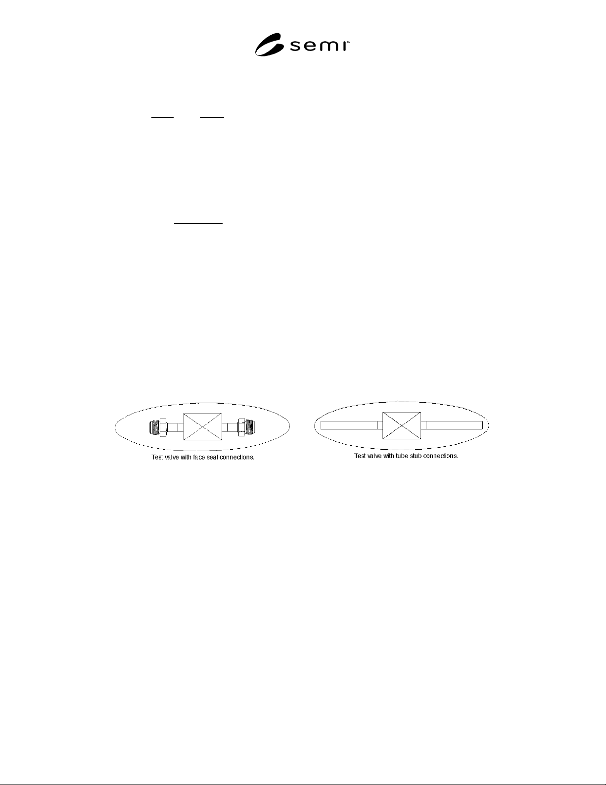
7.1.1 The test valve can be any high purity valve, or a
combination of valve with tube connections, fittings
connection, or expanders which are normally attached
as part of the valve assembly as purchased. It is
important to note that the definition of the “test valve”
is inclusive of all connections and fittings, as supplied
by the manufacturer. This specifically differs from the
ISA procedure, whereby a method is provided to
differentiate the pressure drop contribution of the
attached fittings. It is recognized that flow coefficients
may vary slightly depending upon the end connection
used. Examples of typical test valves are shown in
Figure 1.
Figure 1
Test Valve with Various Connections