semi合集-English.pdf - 第4247页
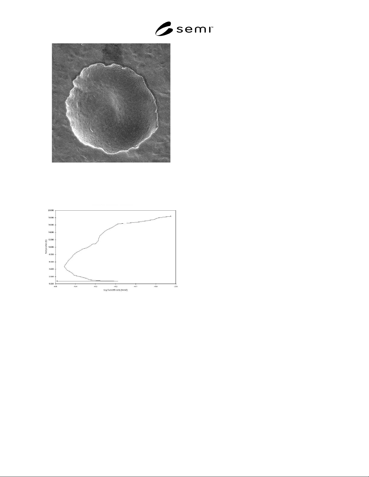
SEMI F77-0703 © SEMI 2003 6 Figure A-1.1 SEM Micrograph of Pit F ormed During CPT Testing. The Pit is Appr oximately 100 Mi crons Across. Figure A-1.2 Current Density as a Functi on of Temperature. The Critical Pitting T…

SEMI F77-0703 © SEMI 2003 5
APPENDIX 1
EXAMPLE OF A CPT TEST PROCEDURE
NOTICE: The material in this appendix is an official part of SEMI F77 and was approved by full letter ballot
procedures.
A1-1 Principle
A1-1.1 Critical pitting temperature (CPT) is an
electrochemical test that determines the localized
corrosion resistance of stainless steel and other alloys.
The test is performed in a solution of sodium chloride
(NaCl). The sample is polarized at 700 mV
SCE
while
the temperature is gradually increased from 0°C at a
rate of 1°C/min. Above some critical temperature,
pitting corrosion will occur signified by a rapid increase
in measured current above 100 µ A/cm
2
for 60 seconds.
The experiment is monitored and controlled using
special software.
A1-2 Precautions
A1-2.1 Use caution with heating mantles, as they can
become very hot.
A1-3 Equipment and Supplies
A1-3.1 Corrosion Test System (potentiostat and
software)
A1-3.2 Chiller (capable of –10°C to 100° C)
A1-3.3 Temperature controller
A1-3.4 Heating Mantle
A1-3.5 Stir Plate/Bar (Immersible)
A1-3.6 Glass cell (adapted to contain electrodes,
probes, and cooling coil)
A1-3.7 Counter electrodes (graphite rods)
A1-3.8 Reference electrode (saturated calomel) and
luggin probe
A1-3.9 Cooling coils
A1-4 Chemicals and Reagents
A1-4.1 Sodium Chloride (ACS Reagent Grade)
A1-4.2 18 MΩ deionized water
A1-5 Procedure
A1-5.1 Turn chiller on and set at -2°C.
A1-5.2 Fill Beaker with 800 ml of 1 M (mole/liter)
NaCl electrolyte (Preferably chilled in refrigerator).
Turn stir plate on and ensure adequate stirring with stir
bar.
A1-5.3 Turn on temperature controllers. Adjust set
point to –1°C. Place lid on beaker and ensure
temperature probe is in solution.
A1-5.4 Place two counter electrodes and one reference
electrode in solution. The reference electrode should be
placed in a luggin probe. The luggin probe tip should
be placed as close to the sample as possible without
interfering with the stir bar. Connect electrical wires to
counter and reference electrodes.
A1-5.5 Turn on computer and potentiostat and start
software.
A1-5.6 After temperature has dropped to 0°C, insert
specimen into test cell. One inch of the sample for tube
stubs should be submerged. Temperature probe should
be touching sample (masked section only).
A1-5.7 Connect electrical wires to specimen and start
the test.
A1-5.8 After approximately 500 seconds during the
initial delay, decrease stir bar rotation speed by one
half.
A1-5.9 After temperature has increased to 10°C,
periodically monitor temperature to ensure proper
heating rate.
A1-5.10 When test is completed, remove the specimen
and rinse with DI water.
A1-5.11 Examine specimen for pit location. If pit is
touching the masked-off or lacquered area, the test is
not valid. See Figure A-1.1 for a SEM micrograph of a
typical pit from a valid CPT test.
A1-5.12 Determine critical pitting temperature. The
critical pitting temperature is the temperature at which
the current density exceeds 100 µA/cm
2
for at least 60
seconds. Figure A-1.2 shows an example of a
temperature vs. current density scan. In this particular
example, the critical pitting temperature was
determined to be 18°C.
SEMI F77-0703 © SEMI 2003 6
Figure A-1.1
SEM Micrograph of Pit Formed During CPT
Testing. The Pit is Approximately 100 Microns
Across.
Figure A-1.2
Current Density as a Function of Temperature. The
Critical Pitting Temperature is the Temperature at
Which the Current Density Exceeds 100
µA/cm
2
for
At Least 60 Seconds.
NOTICE: SEMI makes no warranties or
representations as to the suitability of the standards set
forth herein for any particular application. The
determination of the suitability of the standard is solely
the responsibility of the user. Users are cautioned to
refer to manufacturer' s instructions, product labels,
product data sheets, and other relevant literature,
respecting any materials or equipment mentioned
herein. These standards are subject to change without
notice.
By publication of this standard, Semiconductor
Equipment and Materials International (SEMI) takes no
position respecting the validity of any patent rights or
copyrights asserted in connection with any items
mentioned in this standard. Users of this standard are
expressly advised that determination of any such patent
rights or copyrights, and the risk of infringement of
such rights are entirely their own responsibility.
Copyright by SEMI® (Semiconductor Equipment and Materials
International), 3081 Zanker Road, San Jose, CA 95134. Reproduction o
f
the contents in whole or in part is forbidden without express written
consent of SEMI.

SEMI F78-0304 © SEMI 2003, 2004 1
SEMI F78-0304
PRACTICE FOR GAS TUNGSTEN ARC (GTA) WELDING OF FLUID
DISTRIBUTION SYSTEMS IN SEMICONDUCTOR MANUFACTURING
APPLICATIONS
This practice was technically approved by the Global Gases Committee and is the direct responsibility of the
North American Gases Committee. Current edition approved by the North American Regional Standards
Committee on October 16, 2003. Initially available at www.semi.org February 2004; to be published March
2004. Originally published July 2003.
1 Purpose
1.1 The purpose of this practice is to provide
procedures for welding stainless steels and other
corrosion resistant metals and alloys (CRAs) for fluid
(liquid or gas) distribution systems in semiconductor
manufacturing applications. Welds performed
following these procedures are of sufficient quality to
provide the required system purity, weld integrity, and
weld strength for use in semiconductor manufacturing
applications.
2 Scope
2.1 This practice provides procedures for gas tungsten
arc (GTA) autogenous butt joint welds of stainless steel
and other CRAs in fluid distribution systems. The fluid
distribution system includes tubing, pipe, fittings,
valves, subassemblies and components that contain and
distribute fluid.
NOTICE: This practice does not purport to address
safety issues, if any, associated with its use. It is the
responsibility of the users of this standard to establish
appropriate safety health practices and determine the
applicability of regulatory or other limitations prior to
use.
3 Limitations
3.1 The stainless steels covered by this practice are
limited to the austenitic and superaustenitic grades of
stainless steel.
3.2 Corrosion resistant metals and alloys covered by
this practice are limited to solid solution grades of
nickel alloys and solid solution grades of titanium
alloys.
3.3 This practice applies only to autogenous GTA
circumferential butt joint welds performed on fluid
distribution system components 6 inches or less in
diameter.
3.4 This practice applies only to automatic,
mechanized, or machine GTA welding processes.
3.5 This practice applies only to welds performed with
no fillers and no fluxes.
3.6 This practice does not apply to pressure vessel or
process chamber welds.
4 Referenced Standards
NOTE 1: The following documents become part of the
practice to the extent that they are included herein.
4.1 SEMI Standards
SEMI F20 — Specification for 316L Stainless Steel
Bar, Extruded Shapes, Plate, and Investment Castings
for Components Used in High Purity Semiconductor
Manufacturing Applications
SEMI F81 — Specification for Visual Inspection and
Acceptance of Gas Tungsten Arc (GTA) Welds in Fluid
Distribution Systems in Semiconductor Applications
4.2 ANSI/ASME Standards
1
ANSI/ASC Z49.1 — Safety in Welding, Cutting, and
Allied Processes
BPE — Bioprocessing Equipment Standard
B16.25 — Butt Welding Ends
B31.3 — Process Piping
Boiler and Pressure Vessel Code — Section IX,
Qualification Standard for Welding and Brazing
Procedures, Welders, Brazers, and Welding and
Brazing Operators
4.3 ASTM Standards
2
A269 — Specification for Seamless and Welded
Austenitic Stainless Steel Tubing for General Service
1 American National Standards Institute, New York Office: 11 West
42nd Street, New York, NY 10036, USA. Telephone: 212.642.4900;
Fax: 212.398.0023 Website: www.ansi.org
2 American Society for Testing and Materials, 100 Barr Harbor
Drive, West Conshohocken, Pennsylvania 19428-2959, USA.
Telephone: 610.832.9585, Fax: 610.832.9555, Website:
www.astm.org