semi合集-English.pdf - 第109页
SEMI E10-0304 E © SEMI 1986, 2004 23 R1-5.6.1.6 The state va lue function f or IPF1 = K × PM1. The equival ent truth table is trivial and is therefore not shown. R1-5.6.2 Example 2 — This example, as shown i n Figure R1-…
SEMI E10-0304
E
© SEMI 1986, 2004 22
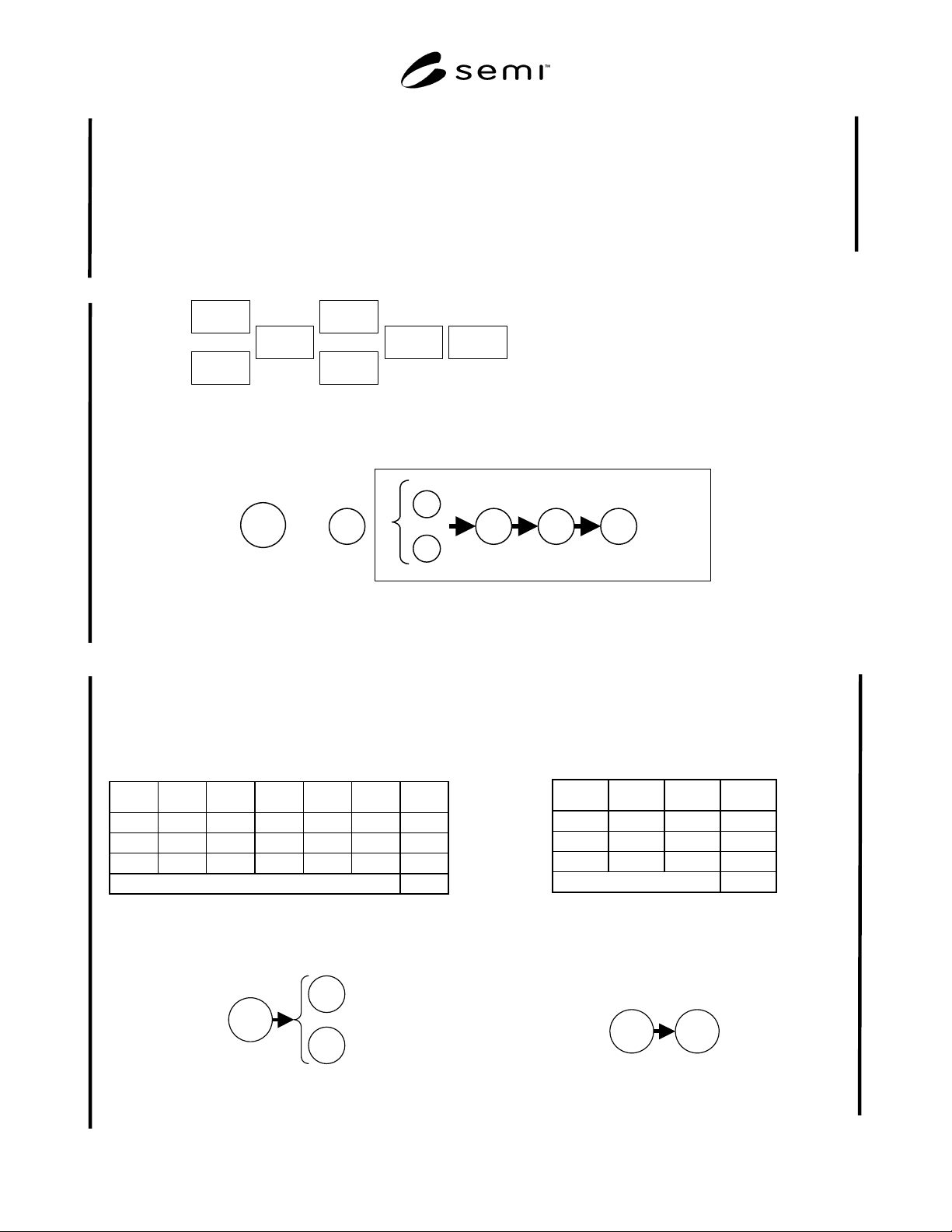
R1-5.6.1 Example 1 — This example, shown in Figure
R1-4, is of a multi-path cluster tool with seven
modules. L1 and L2 are load lock modules that are used
to load units into the tool. A single transport arm, T,
performs all point-to-point transportation. The first
process module visited by any unit is either PM1 or
PM2, after which every unit visits PM3. Lastly, L3 is a
load lock that is used to unload units from the multi-
path cluster tool.
R1-5.6.1.1 The key group, K, as shown in Figure R1-5,
is made up of the three load locks and the transport,
which are the common support modules for this multi-
path cluster tool used by any unit. Since all modules
visit PM3 regardless of any IPF distinction, PM3 also is
included in the key group in order to simplify
calculation. Any other system-level failure issues may
be allocated to the abstract platform module, P.
Li
= Load Lock i, i = 1, 2, 3
PMj = Process Module j, j = 1, 2, 3
T = Transport Module
T
L1
L2
PM1
PM2
PM3 L3
Figure R1-4
Multi-Path Cluster Tool Modules, Example 1
L1
L2
T L3
K
=
P
PM3
Figure R1-5
Key Group, Example 1
R1-5.6.1.2 The state value function for the key group is
K = P × [1 − (1 − L1) × (1 − L2)] × T × L3
×
PM3.
For reference, the equivalent truth table for this logic is
shown in Table R1-1:
Table R1-1 Truth Table for Key Group, Example 1
P L1 L2 T L3 PM3 K
1 1 1 1 1 1 1
1 1 0 1 1 1 1
1 0 1 1 1 1 1
else 0
R1-5.6.1.3 IPF1 is a general IPF that uses the key
group and either process module PM1 or PM2, as
shown in Figure R1-6.
PM1
PM2
K
Figure R1-6
IPF1, Example 1
R1-5.6.1.4 The state value function for IPF1 = K
×
[1
− (1 − PM1)
×
(1 − PM2)]. The equivalent truth table
is shown in Table R1-2:
Table R1-2 Truth Table for the State Function,
Example 1
K PM1 PM2 IPF1
1 1 1 1
1 1 0 1
1 0 1 1
else 0
R1-5.6.1.5 IPF2 represents a process engineering issue
where PM2 is not sufficiently matched in performance
to PM1. Therefore for certain processes, all units are
restricted to go through PM1 only as shown in Figure
R1-7.
PM1
K
Figure R1-7
IPF2, Example 1
SEMI E10-0304
E
© SEMI 1986, 2004 23
R1-5.6.1.6 The state value function for IPF1 = K
×
PM1. The equivalent truth table is trivial and is
therefore not shown.
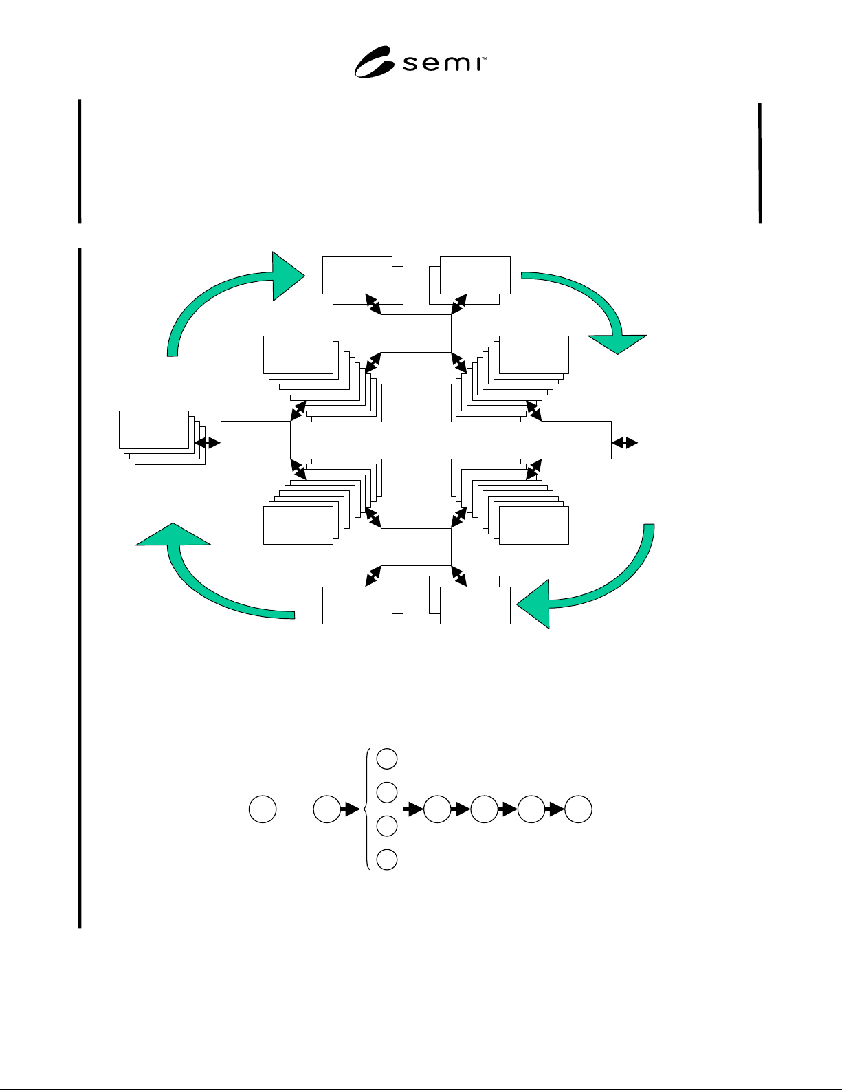
R1-5.6.2 Example 2 — This example, as shown in
Figure R1-8, is of a more complicated coat/develop
system that has 56 total modules, including four load
locks (L1-L4), four common transport robots (R1-R4),
four coat stations, four develop stations, and four arrays
of heat/chill plates with ten modules in each array.
R1-5.6.2.1 The key group, K, contains the platform,
the four load locks, and the four transport robots, as
shown in Figure R1-9. There are no process modules
that are used in every IPF, therefore no process modules
appear in K.
R1
R2
R3
R4
10X Heat /
Chill
10X Heat /
Chill
10X Heat /
Chill
10X Heat /
Chill
Coat
1,2
Coat
3,4
Develop
1,2
Develop
3,4
L
1, 2, 3, 4
To
E
xposure
Figure R1-8
Modules For A Coat/Develop System
L1
L2
L3
L4
R1 R2 R3 R4
K=
P
Figure R1-9
Key Group Modules, Example 2
SEMI E10-0304
E
© SEMI 1986, 2004 24
R1-5.6.2.2 The state value function for the key group is K = P
×
[1 − Π
i = 1 to 4
(1 − Li)] × Π
j=1 to 4
Rj, which can be
expanded to:
K = P × [1 − (1 − L1) × (1 − L2)
×
(1 − L3)
×
(1 − L4)]
×
R1
×
R2
×
R3
×
R4
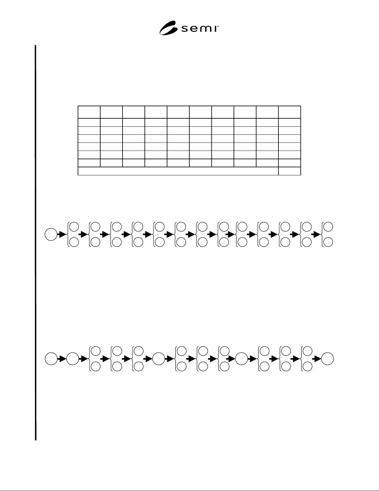
R1-5.6.2.3 The equivalent truth table is shown in Table R1-3:
Table R1-3 Truth Table for State Function, Example 2
P L1 L2 L3 L4 R1 R2 R3 R4 K
0 any any any any any any any any 0
1 0 0 0 0 any any any any 0
any any any any any 0 any any any 0
any any any any any any 0 any any 0
any any any any any any any 0 any 0
any any any any any any any any 0 0
else 1
NOTE 7: This truth table emphasizes the subsets that bring the key group “down,” which are called minimum cut sets, rather
than the subsets that keep the key group “up,” called minimum path sets.
R1-5.6.2.4 IPF1 has 13 steps and each step has two alternative modules, as shown in Figure R1-10.
K
step 1
step 2
step 3
step 4
step 5
step 6
step 7
step 8
step 9
step 10
step 11
step 12
step 13
Figure R1-10
Module Configuration For IPF1, Example 2
R1-5.6.2.5 The state value function for IPF1 = K
×
Π
i=1 to 13
[1 − (1 − PM
i,1
)
×
(1 − PM
i,2
)]. The equivalent truth
table is highly redundant and is therefore omitted.
R1-5.6.2.6 IPF2 has the same 13 steps as IPF1. However due to process matching issues, all units are restricted to a
single process module at steps 1, 5, 9, and 13, as shown in Figure R1-11.
K
step 1
step 2
step 3
step 4
step 5
step 6
step 7
step 8
step 9
step 10
step 11
step 12
step 13
Figure R1-11
Module Configuration For IPF2, Example 2
R1-5.6.2.7 The state value function for IPF2 = K
×
PM
1,1
×
PM
5,1
×
PM
9,1
×
PM
13,1
×
Π
i={2-4, 6-8, 10-12}
[1 − (1 −
PM
i,1
) × (1 − PM
i,2
)]