semi合集-English.pdf - 第5383页
SEMI M55.2-0705 © SEMI 2005 2 Property Dimension SURFACE ORIENTATION #1, #2 Tilt angle (see Figure 2 in SEMI M55) Option 2: “off axis (11 20)” 4.0° 0.5° parallel to edge of prima r y flat away from secondary flat #3 …
SEMI M55.2-0705 © SEMI 2005 1
SEMI M55.2-0705
SPECIFICATION FOR 76.2 mm ROUND POLISHED
MONOCRYSTALLINE 4H AND 6H SILICON CARBIDE WAFERS
This specification was technically approved by the global Compound Semiconductor Materials Committee.
This edition was approved for publication by the global Audits and Reviews Subcommittee on May 20, 2005.
It was available at www.semi.org in June 2005 and on CD-ROM in July 2005.
1 Purpose
1.1 This subordinate standard detail the dimensional values and other information required for 76.2mm polished
monocrystalline silicon carbide wafers.
2 Scope
2.1 The complete specification for this product includes all general requirements of SEMI M55, Specification For
Polished Monocrystalline Silicon Carbide Wafers.
NOTICE: This standard does not purport to address safety issues, if any, associated with its use. It is the
responsibility of the users of this standard to establish appropriate safety and health practices and determine the
applicability of regulatory or other limitations prior to use.
3 Limitations
3.1 The backside finish properties, dopant and resistivity are not addressed, as currently these properties depend
strongly on the quick evolving technology and suitable limits for a standard do not exist.
4 Referenced Standards and Documents
SEMI M13 — Specification for Alphanumeric Marking of Silicon Wafers
SEMI AUX1 — List of Wafer Supplier Identification Codes
5 Terminology
5.1 None.
6 Requirements
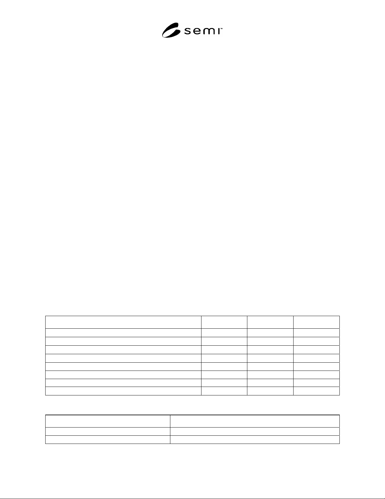
Table 1 Dimension and Tolerance Requirements
Property Dimension Tolerance Units
DIAMETER 76.2
0.25
mm
PRIMARY FLAT LENGTH 22.0
2.0
mm
SECONDARY FLAT LENGTH 11.0
1.5
mm
BOW 0
25
µm
WARP 0 <25 µm
TOTAL THICKNESS VARIATION 0 <25 µm
TOTAL INDICATOR READING 0 <25 µm
THICKNESS 350
25
µm
Table 2 Orientation and Flat Location Requirements
Property Dimension
SURFACE ORIENTATION
#1, #2
Tilt angle (see Figure 2 in SEMI M55)
Option 1:”on axis” 0 + 0.25°
SEMI M55.2-0705 © SEMI 2005 2
Property Dimension
SURFACE ORIENTATION
#1, #2
Tilt angle (see Figure 2 in SEMI M55)
Option 2: “off axis (11
20)”
4.0° 0.5° parallel to edge of primary flat away from secondary flat
#3
Option 3: “off axis (11
20)”
8.0° 0.5° parallel to edge of primary flat away from secondary flat
#3
Option 4: “off axis (1
100)”
4.0° 0.5° parallel to edge of secondary flat away from primary flat
#3
Option 5: “off axis (1
100)”
8.0° 0.5° parallel to edge of secondary flat away from primary flat
#3
ORTHOGONAL MISORIENTATION
5° (See Figure 2 in SEMI M55)
TOLERANCE OF PRIMARY FLAT
ORIENTATION
2°
TOLERANCE OF SECONDARY FLAT
ORIENTATION
#2
5° relative to primary flat
#1
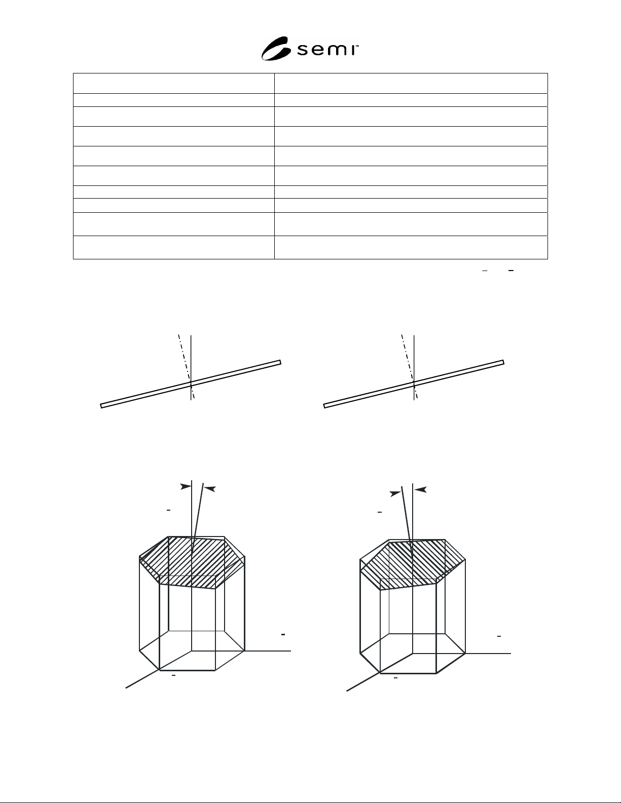
The frame of reference is the (0001)-plane of the crystal. It is the wafer normal on the silicon-face that is tilted towards the given
crystallographic direction. That means that the crystallographic c-axis lies between the secondary/primary flat (for the (1120) / (1100) option
respectively) and the silicon-face surface normal vector (See Figure 1 and 2).
#2
Measured at the center of the wafer.
#3
The angle between primary and secondary flat is defined in Figure 5 in SEMI M55.
Secondary flat
Si-face
Normal vector to
wafer surface
Crystallographic
c-axis
C-face
Primary flat
Si-face
Normal vector to
wafer surface
Crystallographic
c-axis
C-face
Figure 1
Definition of the Direction of the Tilt Angle (Left: Off Axis (11
-
20) -Option, Right Off Axis (1
-
100) Option)
tilt angle tilt angle
off towards [1120]
direction
off towards [1100]
dir ec ti o n
[1120]
direction
[1120]
direction
(1100) plane
(1100) p lan e
Figure 2
Direction of tilt (left: (11
-
20) option, right off axis (1
-
100) -option)
SEMI M55.2-0705 © SEMI 2005 3
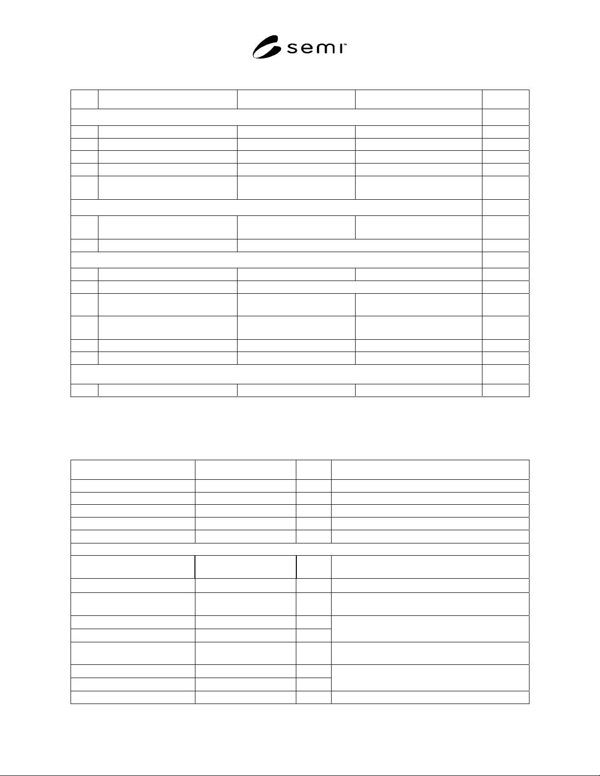
Table 3 Polished Wafer Defect Limits
Item Characteristics Maximum Defect Limit Test Condition Note
Front Surface
1 visible scratches None high intensity, unaided eye 1
2 pits (number) 10 high intensity, unaided eye 1
3 orange peel (area) 10% diffuse, unaided eye 1
4 particles (number) 6 high intensity, unaided eye 1
5 edge chips and indents (number)
3 with maximum length and
width 1.0 mm
Back Surface
3
6 edge chips (number)
3 with maximum length and
width 1.0 mm
7 visible surface inhomogeneity defined by customer and supplier 2
Bulk
8 cracks (number) None diffuse, unaided eye
9 micropipes (mean density) defined by customer and supplier
10 planar defects,
spacing >2 mm (number)
15 diffuse, unaided eye 1
11 planar defects,
spacing 2 mm (affected area)
10% diffuse, unaided eye 1
12 crystallite (area) 5% diffuse, polarisers 1
13 foreign polytypes (area) 10% diffuse 1
Cumulative Defect Area
14 all listed defects of type “area” total 10% 1
#1
The Edge-Exclusion X (See Figure 1 of SEMI M55) is 1 mm.
#2
Dependant on backside finish.
#3
The back side finish properties are not specified.
Table 4 Laser Marking Requirements (see Figure 8 of SEMI M55)
Property Dimension Units
GEOMETRY
dimension A 0.5 mm
dimension B 2.0 mm
dimension C 10.0 mm
#1
MARKING DEPTH
100
µm target value 30µm
CHARACTER SET Defined by SEMI M12 character font and proportions (“SEMI OCR”), not
font size
CHARACTER DIMENSIONS
Option 1: “large”
#3, #4
dimensions according to SEMI M12, readable with
unaided eye
Character Height
1.624 0.025
mm
Character Spacing
1.420 0.025
mm
width and thickness are defined by the proportions
given in SEMI M12
Option 2: “small”
#2, #4
dimensions according to SEMI M13, readable with
unaided eye
Character Height
0.812 0.025
mm
Character Spacing
0.710 0.025
mm
width and thickness are defined by the proportions
given in SEMI M13